Wheel rotation device

a technology for rotating devices and wheels, which is applied in the direction of lifting devices, wheel mounting apparatus, transportation and packaging, etc., can solve the problems of a lack of mechanical assistance for rotation, failure of the kickstand or a toppling of the motorcycle upon the rider, and the limited function of the patent device with the present day motorcycle, etc., to achieve convenient storage and easy disassembly

Inactive Publication Date: 2007-06-21
MEYER JAMES S +1
View PDF18 Cites 21 Cited by
  • Summary
  • Abstract
  • Description
  • Claims
  • Application Information

AI Technical Summary

Benefits of technology

[0029] Another object of the present invention is to provide a motorcycle wheel cleaning, inspection and maintenance device that is constructed of components easily disassembled for parts replacement and service.
[0030] Another object of the present invention is to provide a motorcycle wheel cleaning, inspection and maintenance device that is designed to be compact and conveniently stored on end or wall mountable.

Problems solved by technology

These patented devices have limited function with present day motorcycles.
The patented devices though lack the mechanical assistance for rotation, or provision to apply mechanical assistance, and also do not center a wheel when placed thereupon.
During usage, the patented devices elevate a wheel at a height that allows turning of the front fork which tips a motorcycle excessively.
Excessive tipping causes a pronounced lean upon a kickstand which may lead to failure of the kickstand or a toppling of the motorcycle upon a rider.
While the above-described devices fulfill their respective, particular objectives and requirements, the aforementioned patents do not describe a wheel rotation device that centers wheels placed thereupon and that allows for mechanically rotating wheels as needed.
Further, the wheel rotation device substantially departs from the conventional concepts and designs of the prior art.

Method used


Image

  • Wheel rotation device
  • Wheel rotation device
  • Wheel rotation device

Examples


Embodiment Construction

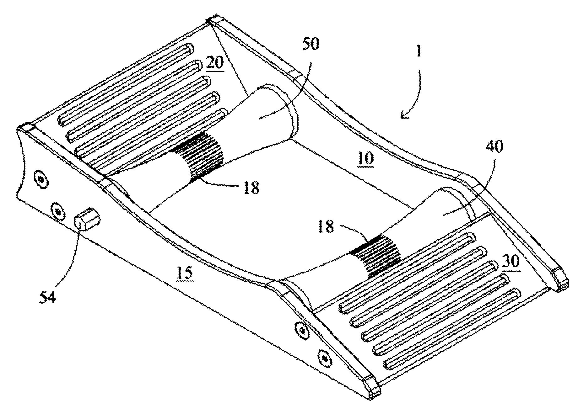
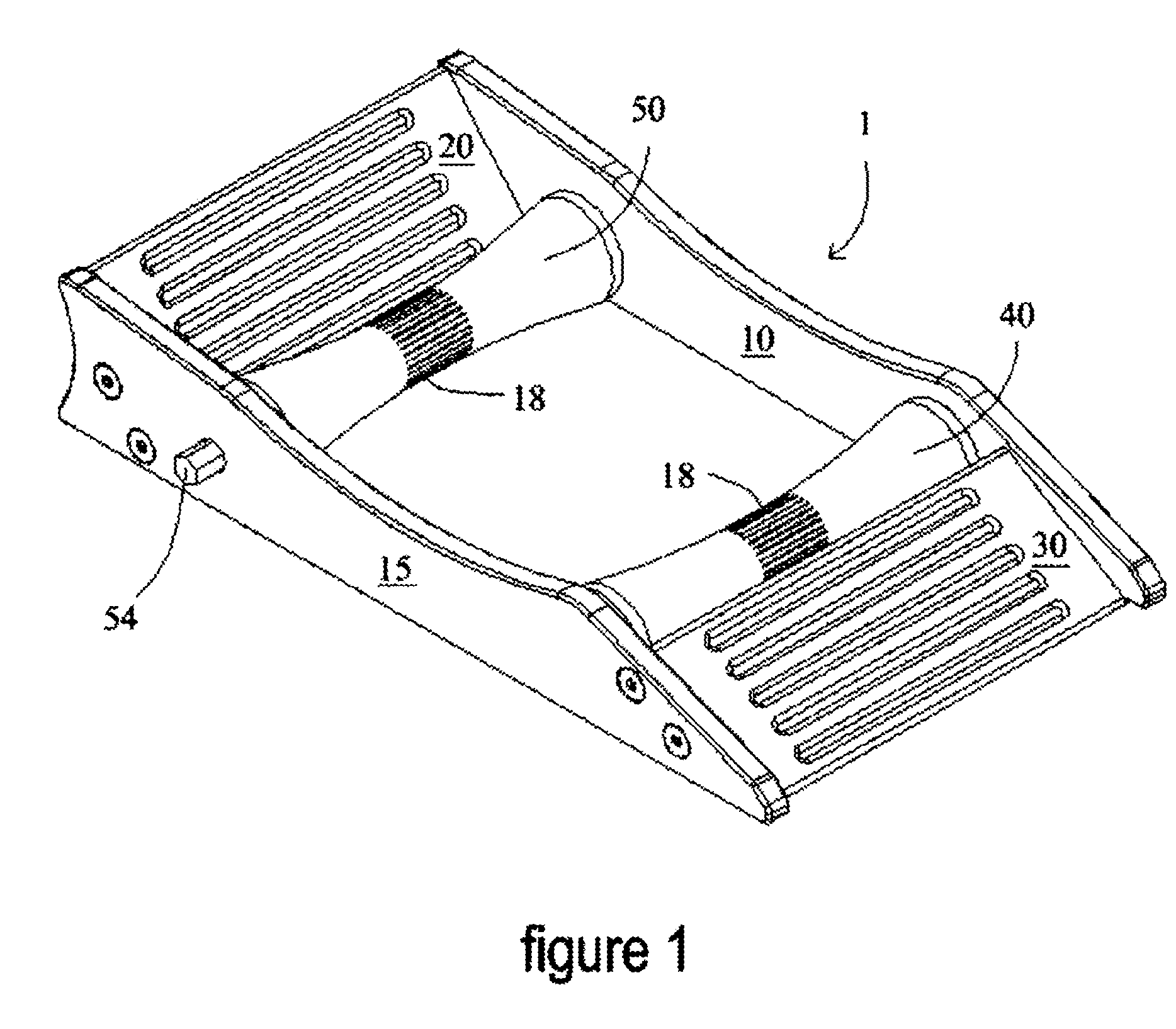
[0042] The present art overcomes the prior art limitations by providing a wheel rotation device with contoured and textured rollers that center a wheel when rotated thereupon. FIGS. 1 through 6 illustrate a motorcycle wheel rotation device 1 according to the present invention. This device is generally located and operated upon a flat surface, such as a garage floor, driveway, or roadway. A motorcycle (not shown) is manually moved forward with one wheel onto the ramp 30 which comes to rest upon and between the front roller 40 and the rear roller 50. The rollers are spaced apart and mutually parallel with their longitudinal axes generally perpendicular to the length of the device. The wheel can then be rotated by hand, or with the assistance of the integrated drive spindles, or axles 52, incorporated onto the opposing ends of the rear roller 50 situated closest to the backstop 20 for cleaning, inspection and maintenance of the motorcycle wheel and tire.

[0043] The present invention ge...


PUM


Abstract

A wheel rotation device assists in cleaning, inspection and maintenance of wheels. The device has a ramp, a backstop, and two contoured rollers, fastened to rails. The device operates upon a flat surface such as a garage floor or driveway, and avoids slipping from friction with the flat surface and a non-skid treatment on to the underside of the rails. The ramp allows the motorcycle to be rolled forward onto the rollers that centers the motorcycle wheel upon and between the rollers as it is manually rotated. The backstop limits forward movement of the motorcycle wheel to within the rear of the device. The rear roller, nearest the backstop, has spindles projecting through the rails and have machined ends that accept a tool to rotate the motorcycle wheel.

Description

CROSS REFERENCE TO RELATED APPLICATION [0001] This non-provisional application claims priority to the provisional application Ser. No. 60 / 751,904 filed on Dec. 21, 2005 which is commonly owned by the same inventors.BACKGROUND OF THE INVENTION [0002] The present invention relates generally to the cleaning, inspection, and maintenance of wheels, such as motorcycle wheels. Specifically, the present invention pertains to a device for rotating a wheel while mounted upon an axle without power or movement of the wheel and the use of lifting devices. [0003] After a few miles on the road, or even off the road, motorcycle wheels accumulate dust, grime, and dirt. Riders tolerate some dust and grime upon the motorcycle wheels to show the activity of the motorcycle to others. In time, riders once again desire shiny and clean motorcycle wheels. Over a longer period of time, dust, grime, and dirt may damage a wheel or other mechanical parts and components of a motorcycle. With the desire for shiny...

Claims


Application Information

Patent Timeline
Patent Type & Authority Applications(United States)
IPC IPC(8): A47F7/04B65G13/00B60B29/00
CPCB60B29/00B66F7/243
Inventor MEYER, JAMES S.MEYER, JONATHAN G.
Owner MEYER JAMES S
Why Eureka
Try Eureka