
Applicator that is used to apply one or more materials to a surface

a technology of a surface and an application device, which is applied in the field of applications, can solve the problems of unsuitable use for adequately applying a material to a surface, difficult to squeeze the material from the packet, and difficulty in cleaning up and/or storage after use, and achieves the effect of reducing mess and high viscosity

Inactive Publication Date: 2007-06-21
KIMBERLY-CLARK WORLDWIDE INC
View PDF33 Cites 23 Cited by
  • Summary
  • Abstract
  • Description
  • Claims
  • Application Information

AI Technical Summary

Benefits of technology

[0006] The present invention is an applicator that is able to store a material and then apply the material to a surface. The applicator is able to generate a force that causes the material to be expelled from the applicator even when the material has a relatively high viscosity. In addition, the applicator is able to apply the material to a surface without the use of another tool and in a manner that reduces the mess which is typically associated with applying a material to a surface.

Problems solved by technology

One of the drawbacks with many of these types of devices is that they are often large and cumbersome which makes them difficult to clean up and / or store after use.
However, the design of most small disposable packets typically makes them unsuitable for use to adequately apply a material to a surface.
As an example, the relatively high viscosity of some materials which are commonly stored in such packets makes it is difficult to squeeze the material from the packet without creating a mess or using an excessively large force.

Method used


Image

  • Applicator that is used to apply one or more materials to a surface
  • Applicator that is used to apply one or more materials to a surface
  • Applicator that is used to apply one or more materials to a surface

Examples


Embodiment Construction

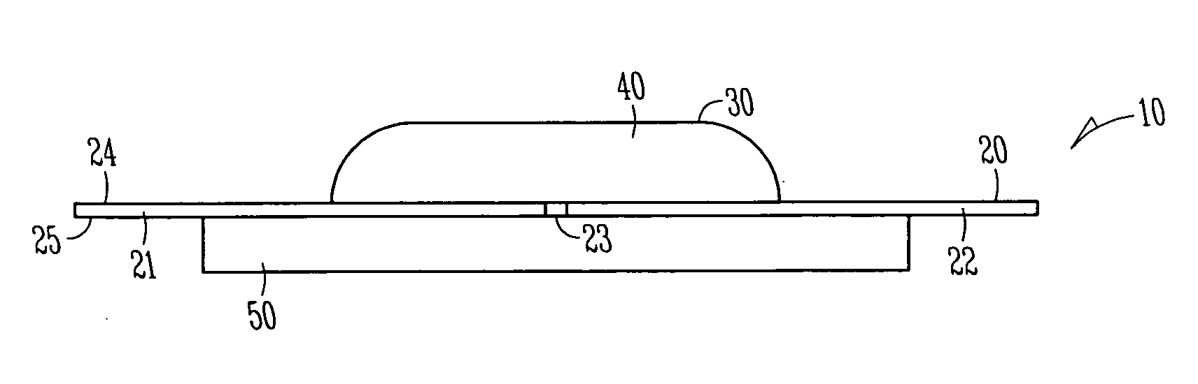
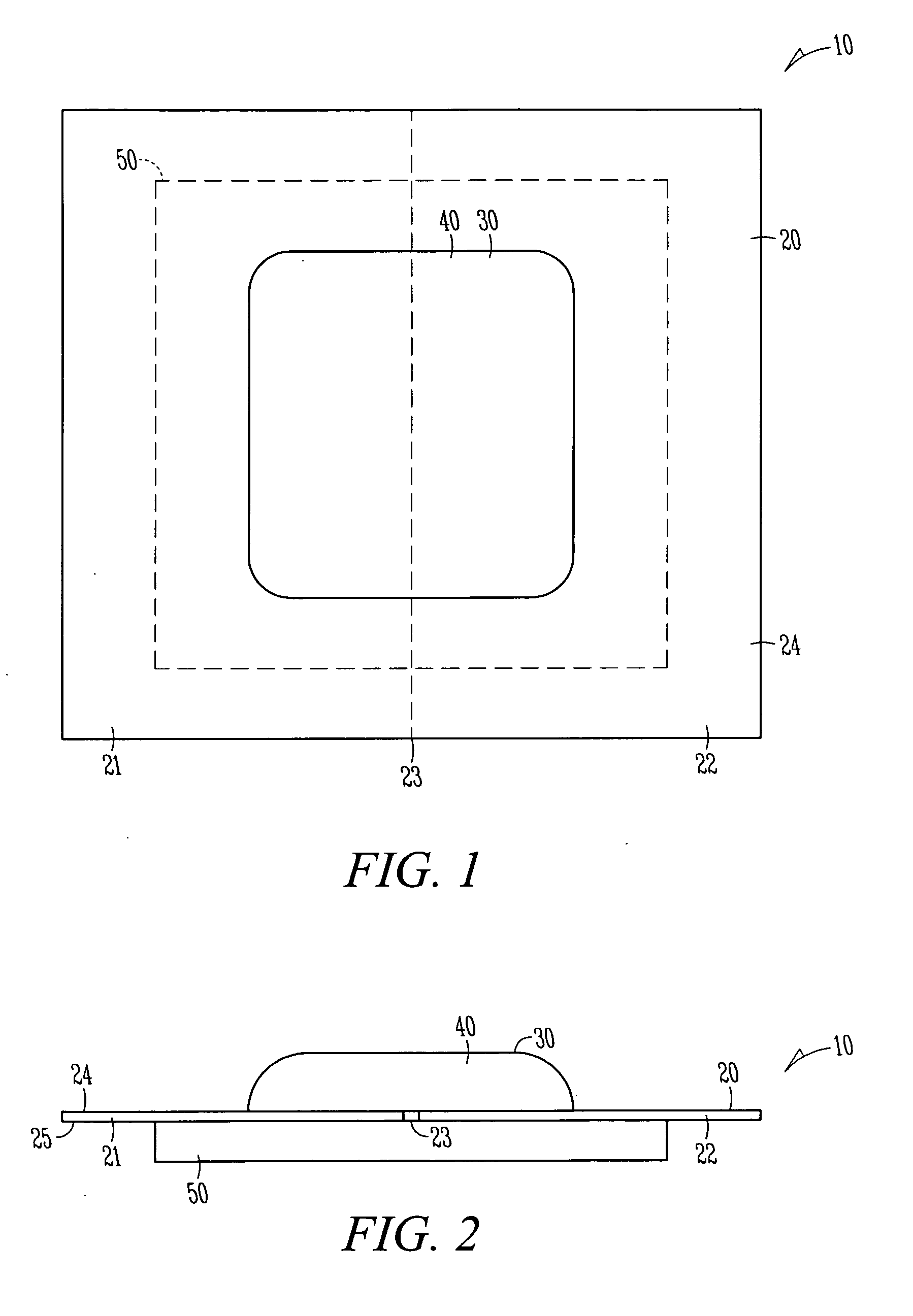
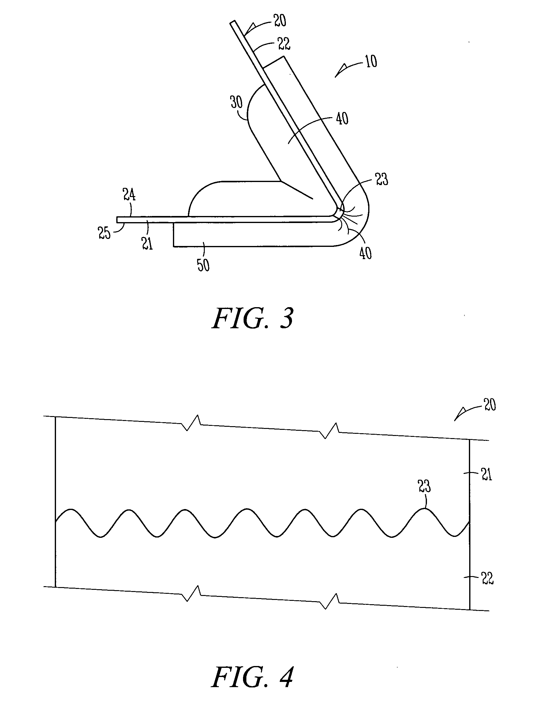
[0039]FIGS. 1-3 illustrate an example embodiment of an applicator 10. The applicator 10 includes a base 20 that has a first section 21, a second section 22 and a weakened section 23 which is between the first and second sections 21, 22. The applicator 10 further includes a bladder 30 that is positioned on one side 24 of the base 20 and a material 40 that is stored within the bladder 30. The applicator 10 further includes a dispensing member 50 that is positioned on an opposite side 25 of the base 20 to the bladder 30 such that when the base 20 is folded at the weakened section 23, the first and second sections 21, 22 force the material 40 from the bladder 30 into the dispensing member 50 (see FIG. 3).

[0040] Once the material 40 is forced into the dispensing member 50, the dispensing member 50 may be used to apply the material 40 to a surface (not shown). As the base is further folded to bring the first and second sections 21, 22 closer together, the first and second sections 21, 22...


PUM

PropertyMeasurementUnit
forceaaaaaaaaaa
sinusoidal shapeaaaaaaaaaa
shapeaaaaaaaaaa

Abstract

In one example embodiment, the applicator includes a base that has a first section, a second section and a weakened section which is between the first and second sections. The applicator further includes a first bladder and a second bladder. The first bladder is connected to a first outlet and the second bladder is connected to a second outlet. The first and second bladders are positioned on one side of the base such that neither of the first and second bladders overlaps the weakened section of the base. The applicator further includes a first material that is stored within the first bladder and a second material that is stored within the second bladder. When the base is folded at the weakened section, the first and second sections of the base force the materials from the first and second bladders through the respective first and second outlets.

Description

FIELD [0001] The present invention relates to an applicator, and in particular to an applicator that is used to apply one or materials to a surface. BACKGROUND [0002] There are many circumstances where one or more materials need to be applied to a surface. As examples, materials are sometimes applied to a surface for use as cleaners, sealing agents, caulking agents, cosmetics and health care agents (among other uses). [0003] A variety of different types of devices are commonly used to store a material and then apply the material to a surface. One of the drawbacks with many of these types of devices is that they are often large and cumbersome which makes them difficult to clean up and / or store after use. [0004] There are some small disposable packets that are sometimes used to store a material and then apply a material to a surface. However, the design of most small disposable packets typically makes them unsuitable for use to adequately apply a material to a surface. [0005] As an ex...

Claims


Application Information

Patent Timeline
Patent Type & Authority Applications(United States)
IPC IPC(8): B67D5/60B65D35/00B67D7/78
CPCA45D34/04A45D37/00A45D2200/1018A45D2200/1045B65D75/58
Inventor CHEN, FUNG-JOULINDSAY, JEFFREY D.SCHMIDT, PAUL R.
Owner KIMBERLY-CLARK WORLDWIDE INC
Learn More