System and method for direct liquid cooling of electric machines

a technology of electric machines and cooling systems, applied in the direction of dynamo-electric machines, electrical apparatus, windings, etc., can solve the problems of unsatisfactory heat transfer to the core, components that are inoperable, and typically do not sufficiently inhibit heat transfer in rotating machines

Inactive Publication Date: 2007-06-21
HONEYWELL INT INC
View PDF15 Cites 10 Cited by
  • Summary
  • Abstract
  • Description
  • Claims
  • Application Information

AI Technical Summary

Problems solved by technology

The wire coils may produce heat during machine operation and may, consequently, undesirably transfer the heat to the core.
Although this is adequate for small rotating machines, it typically does not sufficiently inhibit heat transfer in rotating m...

Method used


Image

  • System and method for direct liquid cooling of electric machines
  • System and method for direct liquid cooling of electric machines
  • System and method for direct liquid cooling of electric machines

Examples


Embodiment Construction

[0015] The following detailed description of the invention is merely exemplary in nature and is not intended to limit the invention or the application and uses of the invention. Furthermore, there is no intention to be bound by any theory presented in the preceding background of the invention or the following detailed description of the invention.

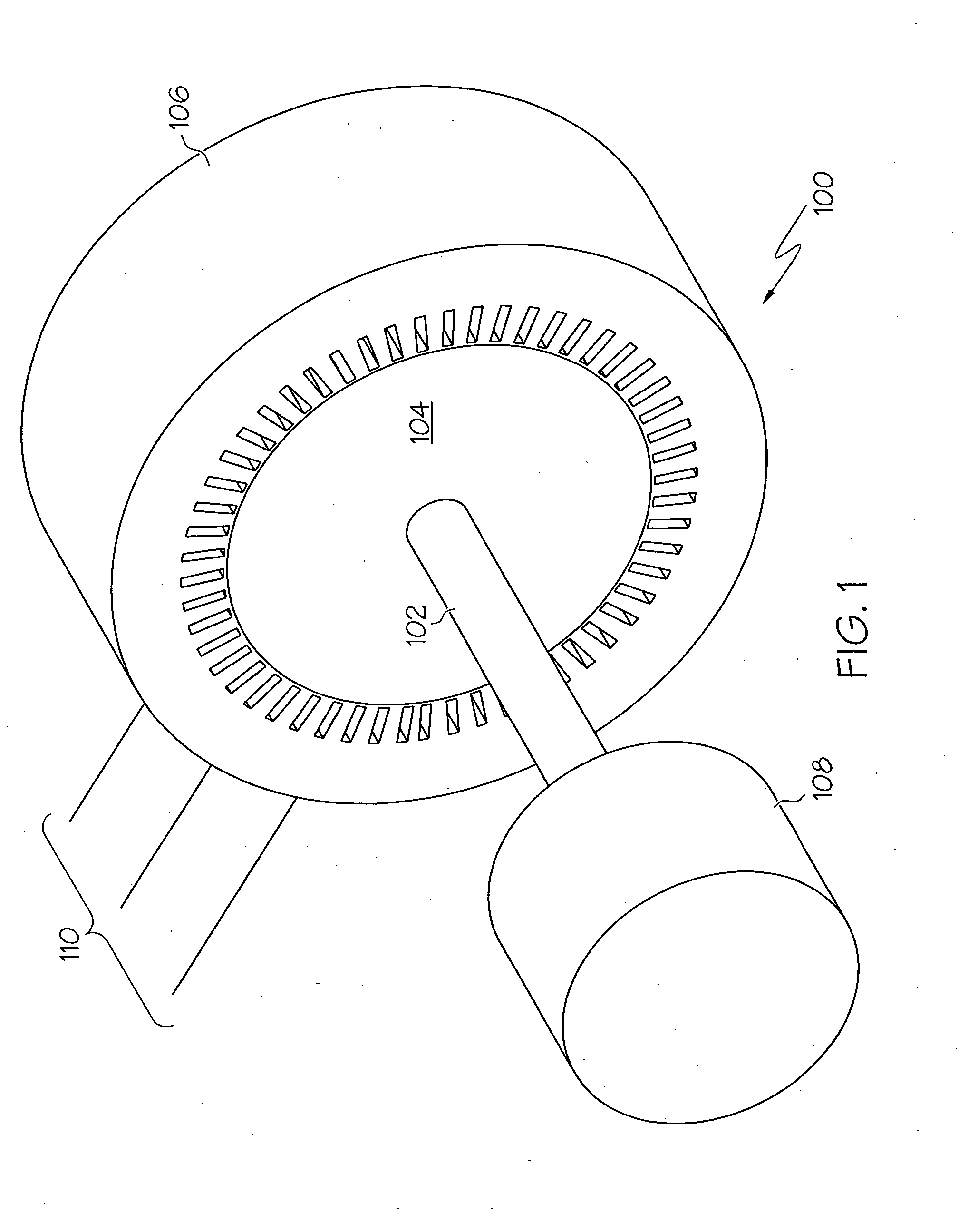
[0016] A simplified mechanical schematic representation of a generalized embodiment of an AC machine 100 is depicted in FIG. 1. The machine 100 may be either an AC motor or an AC generator, and includes a shaft 102, a rotor 104, and a stator 106. A device 108 is coupled to the shaft 102. If the AC machine 100 is a generator, the device 108 is a prime mover for rotating the shaft 102 and the electrical power generated in the stator 106 is delivered to a load via a set of leads 110 that are coupled to each of the stator windings. If the AC machine 100 is a motor, the device 108 is a load to be rotated by the shaft 102 and power is supplied t...


PUM


Abstract

A system is provided for cooling a stator coil of a rotating machine. In one embodiment, and by way of example only, the system includes a stator core, a radial core opening, and a sleeve. The stator core has an axially extending slot formed therein, an outer circumferential surface, and an inner circumferential surface. The radial core opening extends from the stator core outer circumferential surface to the axially extending slot. The sleeve is disposed within the axial slot and configured to surround the stator coil. The sleeve has a cooling fluid supply port formed therein that is aligned with the radial core opening.

Description

TECHNICAL FIELD [0001] The present invention relates to rotating electrical machines and, more particularly, to a cooling system for a stator of a rotating electrical machine. BACKGROUND [0002] Aircraft systems include various types of rotating electrical machines, such as alternating current (AC) motors and generators of various designs. Generally, an AC machine includes a rotor and a stator. If the machine is operated as a motor, electrical power is supplied to the stator to develop a rotating electrical field. This rotating electrical field generates a torque in the rotor causing it to rotate. If the machine is operated as a generator, electrical power is supplied to the rotor to generate a magnetic field. A prime mover is coupled to the rotor causing it, and thus the generated magnetic field, to rotate. This rotating magnetic field induces a voltage into the stator, which supplies electrical power to a load. [0003] A stator for AC machines may typically include a stator core hav...

Claims


Application Information

Patent Timeline
IPC IPC(8): H02K9/00H02K9/20
CPCH02K3/24
Inventor DOWN, EDWARD M.PEARSON, WAYNE T.XU, MINGZHOU
Owner HONEYWELL INT INC
Why Eureka
Try Eureka