Handheld microwave imaging device

a handheld microwave and imaging device technology, applied in the direction of measuring devices, instruments, antennas, etc., can solve the problems of inability to detect non-metallic objects, inability to reliably and accurately detect metal detector wands, and tedious physical inspection

Inactive Publication Date: 2007-06-21
AGILENT TECH INC
View PDF29 Cites 21 Cited by
  • Summary
  • Abstract
  • Description
  • Claims
  • Application Information

AI Technical Summary

Benefits of technology

[0009] Embodiments of the present invention further provide a method for screening an object using a handheld microwave imaging device including an array of programmable microwave antenna elements. The method includes positioning the array with respect to the object to capture a microwave image of a volume associated with the object, programming each of the microwave antenna elements with a respective direction coefficient to direct microwave illumination towards

Problems solved by technology

However, physical inspection is tedious, unreliable, invasive and wholly objectionable in some cultures.
However, metal detector wands are prone to false alarms, and are not capable of detecting non-metallic objects, such as plastic or liquid explosives, plastic or ceramic handguns or knives and drugs.
Furthermor

Method used


Image

  • Handheld microwave imaging device
  • Handheld microwave imaging device
  • Handheld microwave imaging device

Examples


Embodiment Construction

[0020] As used herein, the terms microwave radiation and microwave illumination each refer to the band of electromagnetic radiation having wavelengths between 0.3 mm and 30 cm, corresponding to frequencies of about 1 GHz to about 1,000 GHz. Thus, the terms microwave radiation and microwave illumination each include traditional microwave radiation, as well as what is commonly known as millimeter wave radiation.

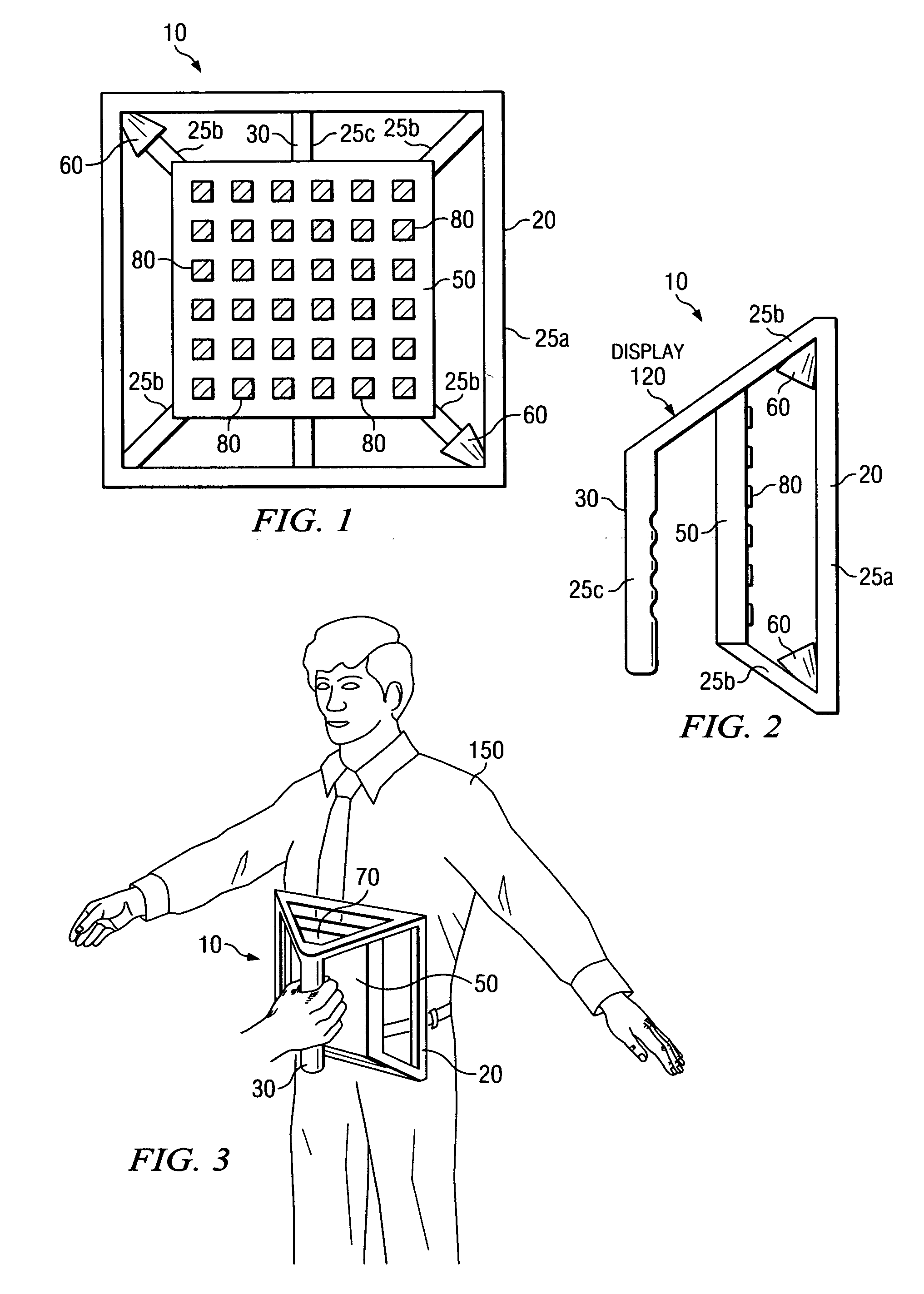
[0021] Referring now to FIGS. 1-3, there is illustrated an exemplary handheld microwave imaging device 10, in accordance with embodiments of the present invention. FIG. 1 is a top view of the handheld microwave imaging device 10, FIG. 2 is a side view of the handheld imaging device 10 and FIG. 3 illustrates an exemplary operation of the handheld microwave imaging device 10. As can be seen in FIGS. 1 and 2, the microwave imaging device 10 includes an array 50 of antenna elements 80, each capable of transmitting, receiving and / or reflecting microwave radiation to capture a micro...


PUM


Abstract

A handheld microwave imaging device provides screening of objects, such as persons and other items. The imaging device includes an antenna array of antenna elements, each capable of being programmed with a respective direction coefficient to direct microwave illumination toward a target associated with the object, and each capable of being programmed with a respective additional direction coefficient to receive reflected microwave illumination reflected from the target. The imaging device further includes a processor operable to measure an intensity of the reflected microwave illumination to determine a value of a voxel within a microwave image of the object. The antenna array is compliantly mounted in a first portion of a support structure, while a second portion of the support structure defines a handle for enabling a user to control movement of the device.

Description

CROSS-REFERENCE TO RELATED APPLICATIONS [0001] This application is related by subject matter to U.S. Application for Pat. Ser. No. ______(Attorney Docket No. 10040151), entitled “A Device for Reflecting Electromagnetic Radiation,” U.S. Application for Pat. Ser. No. ______(Attorney Docket No. 10040580), entitled “Broadband Binary Phased Antenna,” and U.S. Application for Pat. Ser. No. 10 / 996,764, entitled “System and Method for Security Inspection Using Microwave Imaging” all of which were filed on Nov. 24, 2004. [0002] This application is further related by subject matter to U.S. Application for Pat. Ser. No. ______(Attorney Docket No. 10050095), entitled “System and Method for Efficient, High-Resolution Microwave Imaging Using Complementary Transmit and Receive Beam Patterns,” U.S. Application for Pat. Ser. No. 11 / 088,831, entitled “System and Method for Inspecting Transportable Items Using Microwave Imaging,” U.S. Application for Pat. Ser. No. ______(Attorney Docket No. 10050533),...

Claims


Application Information

Patent Timeline
IPC IPC(8): G01S13/89
CPCG01S13/89H01Q3/46
Inventor BAHARAV, IZHAKTABER, ROBERTLEE, GREGORYNEIL, JOHNCORREDOURA, PAULWEEMS, WILLIAMYOUNG, JAMES
Owner AGILENT TECH INC
Why Eureka
Try Eureka