Optical element

a technology of optical elements and elements, applied in the field of optical elements, can solve the problems of hardly acquiring good properties over a wide range of voltage applied, and achieve the effect of good optical properties, easy change, and great

Inactive Publication Date: 2007-06-21
JAPAN SCI & TECH CORP
View PDF6 Cites 229 Cited by
  • Summary
  • Abstract
  • Description
  • Claims
  • Application Information

AI Technical Summary

Benefits of technology

[0028] Accordingly, an object of one embodiment of this invention is to provide an optical element that has good optical properties, which can be changed easily and greatly while being maintained.

Problems solved by technology

They have a problem, however.
They can hardly acquire good properties over a wide range of the voltage applied.

Method used


Image

  • Optical element
  • Optical element
  • Optical element

Examples


Embodiment Construction

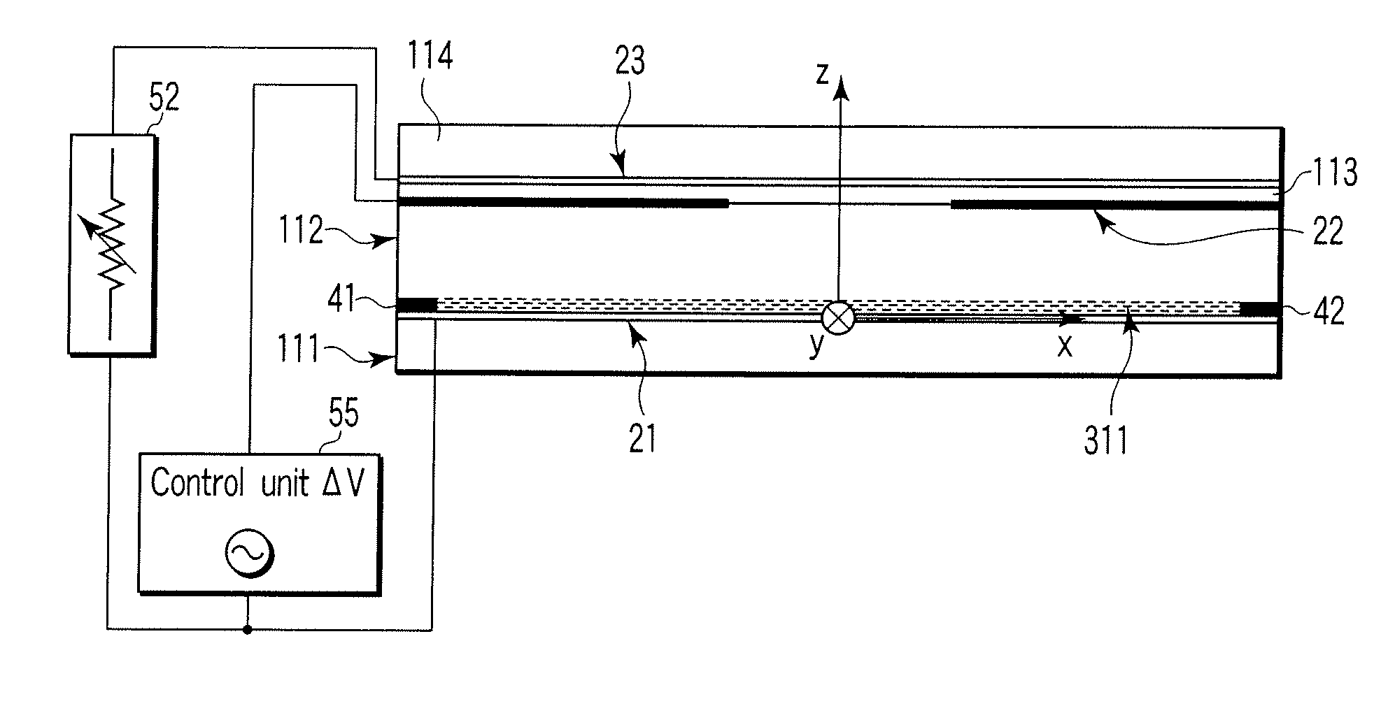
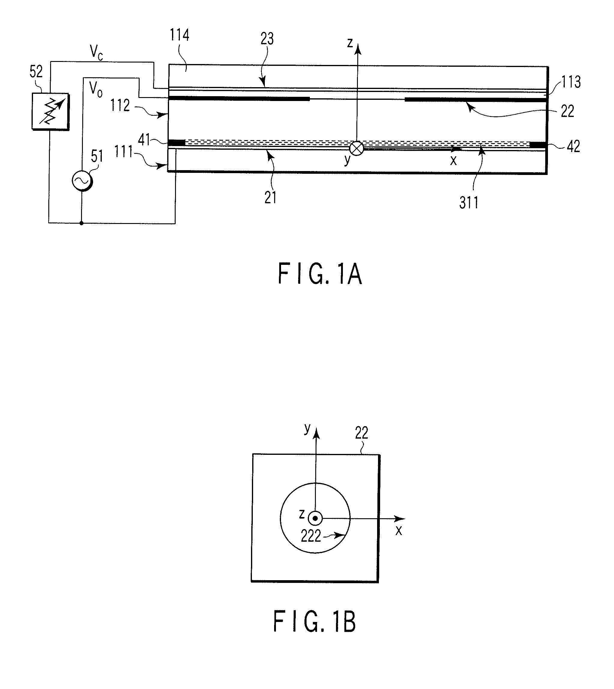
[0059] Embodiments of the present invention will be described in detail, with reference to the accompanying drawings. FIGS. 1A and 1B, number 111 designates a first substrate (transparent glass plate). A first electrode 21 (made of ITO) is formed on the inner surface of the first substrate 111. On the side of the first electrode 21, a second substrate 112 (transparent glass plate) is arranged, facing the first electrode 21 and extending parallel thereto. Outside the second substrate112, a second electrode 22 (made of Al) is formed. As shown in FIG. 1B, the second electrode 22 has a circular hole 222 (having a diameter of, for example, 4.5 mm).

[0060] A liquid crystal layer 311 (having a thickness of, for example, 130 μm) is formed between the first electrode 21, which is formed on the first substrate 111, and the second substrate 112. Reference numbers 41 and 42 denote spacers that define the liquid crystal layer 311.

[0061] Further, an insulating layer 113 (e.g., glass layer as thi...


PUM


Abstract

The focal distance can be greatly changed by performing an electrical control in an optical element. The optical element comprises a first substrate having a first electrode, a second substrate, a second electrode arranged outside the second substrate, and a liquid crystal layer provided between the first substrate and the second substrate and constituted by liquid crystal molecules oriented. A first voltage is applied between the first electrode and the second electrode, thereby controlling the orientation of the liquid crystal molecules, whereby the optical element operates. A third electrode is provided on an insulating layer and outside the second electrode. A second voltage independent of the first voltage is applied to the third electrode, thereby changing the optical properties.

Description

CROSS REFERENCE TO RELATED APPLICATIONS [0001] This is a Continuation Application of PCT Application No. PCT / JP2005 / 015464, filed Aug. 25, 2005, which was published under PCT Article 21 (2) in Japanese. [0002] This application is based upon and claims the benefit of priority from prior Japanese Patent Applications No. 2004-246860, filed Aug. 26, 2004; and No. 2005-052626, filed Feb. 28, 2005, the entire contents of both of which are incorporated herein by reference. BACKGROUND OF THE INVENTION [0003] 1. Field of the Invention [0004] The present invention relates to an optical element in which two different voltages are applied between an electrode provided on a substrate constituting a liquid crystal cell and an electrode provided outside the substrate to control the orientation of liquid crystal molecules and in which specific optical properties can be easily adjusted. [0005] 2. Description of the Related Art Liquid crystal has fluidity as liquid and exhibits anisotropy in electro-...

Claims


Application Information

Patent Timeline
Patent Type & Authority Applications(United States)
IPC IPC(8): G09G3/36
CPCG02F1/134309G02F1/29G02F2001/294G02F2201/12G02F1/294G02F1/133G02F1/1335
Inventor SATO, SUSUMUYE, MAO
Owner JAPAN SCI & TECH CORP
Why Eureka
Try Eureka