Exposure apparatus, exposure method, and method for producing device

a technology of exposure apparatus and exposure method, which is applied in the field of exposure apparatus, can solve the problems of difficult to match the substrate surface with respect to the image plane of the projection optical system, insufficient focus margin, and difficult to maintain the desired state, etc., and achieve the effect of suppressing the spread or expansion of the liquid immersion area, suppressing the amount of movement of the interface, and suppressing the large change of the shape of the interfa

Inactive Publication Date: 2007-06-21
NIKON CORP +1
View PDF29 Cites 43 Cited by
  • Summary
  • Abstract
  • Description
  • Claims
  • Application Information

AI Technical Summary

Benefits of technology

[0009] In order to achieve the object as described above, the present invention adopts the following constructions corresponding to FIGS. 1 to 33 as corresponding to embodiments.
[0010] According to a first aspect of the present invention, there is provided an exposure apparatus which exposes a substrate by radiating an exposure light beam onto the substrate through a liquid; the exposure apparatus comprising a projection optical system; and a liquid immersion mechanism which supplies the liquid and which recovers the liquid; wherein the liquid immersion mechanism has an inclined surface which is opposite to a surface of the substrate and which is inclined with respect to the surface of the substrate, and a liquid recovery port of the liquid immersion mechanism is formed on the inclined surface.
[0011] According to the first aspect of the present invention, the liquid recovery port of the liquid immersion mechanism is formed on the inclined surface which is opposed to the surface of the substrate. Therefore, even when the substrate and the liquid immersion area formed on the side of the image plane of the projection optical system are relatively moved, it is possible to suppress any large change of the shape of the interface as well, while suppressing the amount of movement of the interface (gas-liquid interface) between the liquid of the liquid immersion area and the space disposed at the outside thereof. Therefore, it is possible to maintain a desired state for the condition (for example, the size) of the liquid immersion area. Further, it is possible to suppress the spread or expansion of the liquid immersion area.
[0012] According to a second aspect of the present invention, there is provided an exposure apparatus which exposes a substrate by radiating an exposure light beam onto the substrate through a liquid; the exposure apparatus comprising a projection optical system; and a liquid immersion mechanism which supplies the liquid and which recovers the liquid; wherein the liquid immersion mechanism has a flat porti...

Problems solved by technology

If the depth of focus δ is too narrowed, it is difficult to match the substrate surface with respect to the image plane of the projection optical system.
It is feared that the focus margin is insufficient during the exposure operation.
However, if the scanning velocity is increased to be high, then it is difficult to maintain the desired state, for example, for the condition (for example, the size) of the liquid immersion area, and the exposure accuracy and the measurement accuracy, which are to be obtained through the liquid, are consequently deteriorated.
For example, if the liquid immersion area cannot be maintained in the desired state, and any bubble and/or any void (gap) is formed in the liquid, then the exposure light beam, which passes through the liquid, does not arrive at the surface of the substrate satisfa...

Method used


Image

  • Exposure apparatus, exposure method, and method for producing device
  • Exposure apparatus, exposure method, and method for producing device
  • Exposure apparatus, exposure method, and method for producing device

Examples


first embodiment

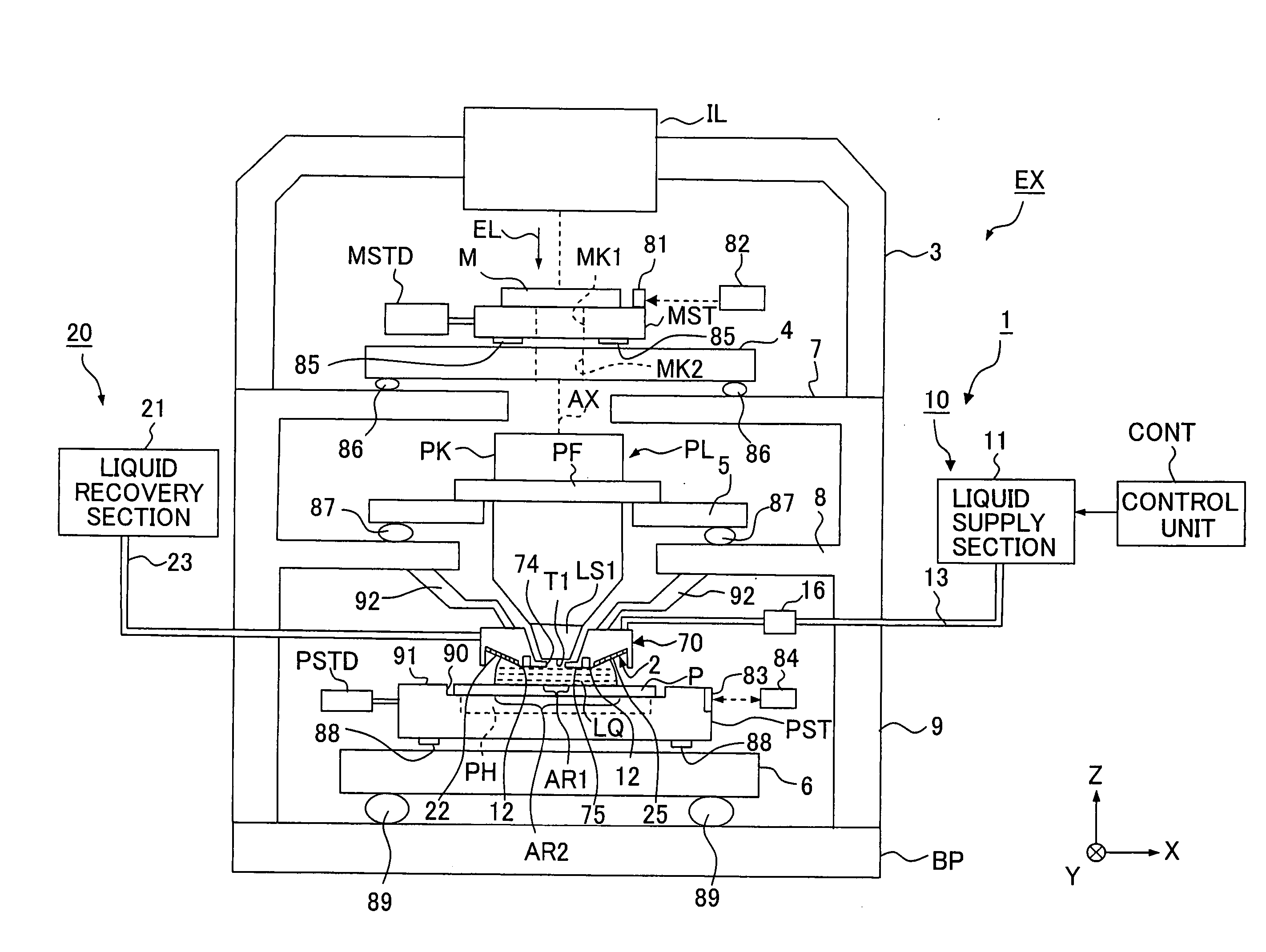
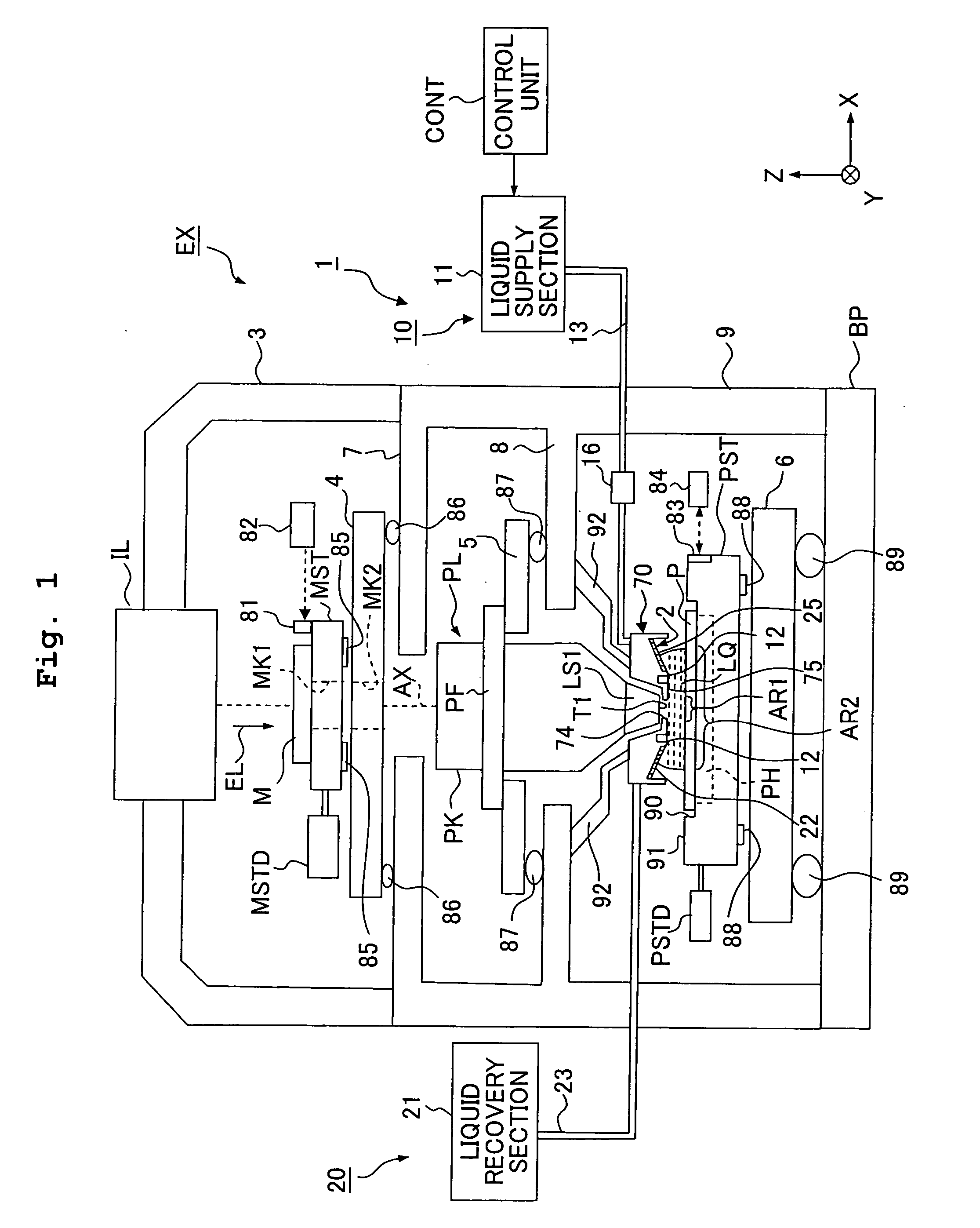
[0059]FIG. 1 shows a schematic arrangement illustrating a first embodiment of the exposure apparatus according to the present invention. With reference to FIG. 1, the exposure apparatus EX includes a mask stage MST which is movable while holding a mask M, a substrate stage PST which is movable while holding a substrate P, an illumination optical system IL which illuminates, with an exposure light beam EL, the mask M held by the mask stage MST, a projection optical system PL which projects an image of a pattern of the mask M illuminated with the exposure light beam EL onto the substrate P held by the substrate stage PST to perform the exposure, and a control unit CONT which integrally controls the operation of the entire exposure apparatus EX.

[0060] The exposure apparatus EX of the embodiment of the present invention is the liquid immersion exposure apparatus in which the liquid immersion method is applied in order that the exposure wavelength is substantially shortened to improve t...

second embodiment

[0128] Next, a second embodiment of the present invention will be explained with reference to FIG. 9. In the following explanation, the constitutive parts, which are the same as or equivalent to those of the embodiment described above, are designated by the same reference numerals, and any explanation of which will be simplified or omitted. In the first embodiment described above, the inclined surface 2 is formed by attaching the thin plate-shaped porous member 25 obliquely with respect to the substrate P. However, as shown in FIG. 9, an inclined surface 2″, for which the distance with respect to the surface of the substrate P is increased at positions separated farther from the optical axis AX of the exposure light beam EL, may be provided on the lower surface of the nozzle member 70, and the liquid recovery port 22 may be formed at a predetermined position (in a predetermined area) of a part of the inclined surface 2″. The porous member 25 may be provided in the liquid recovery po...

third embodiment

[0129]FIG. 10 shows a third embodiment of the present invention. As shown in FIG. 10, a first area 2A, which is included in the lower surface 2 of the porous member 25 and which is disposed near to the optical axis AX, may be formed so that an angle of inclination of the first area 2A with respect to the substrate P is larger than an angle of inclination of a second area 2B with respect to the substrate P, the second area 2B being disposed outside the first area 2A.


PUM


Abstract

Exposure apparatus exposes a substrate by irradiating the substrate with exposure light via a projection optical system and a liquid. The exposure apparatus is provided with a liquid immersion mechanism for supplying the liquid and recovering the liquid. The liquid immersion mechanism has an inclined surface, which is opposite to a surface of the substrate and is inclined with respect to the surface of the substrate, and a liquid recovering port of the liquid immersion mechanism is formed in the inclined surface. A flat portion is provided between the substrate and the projection optical system. A liquid immersion area can be maintained to be small.

Description

[0001] This is a Division of U.S. patent application Ser. No. 11 / 597,745, which is the U.S. National Stage of PCT / JP2005 / 010576 filed Jun. 9, 2005. The disclosure of each of the prior applications is hereby incorporated by reference herein in its entirety.TECHNICAL FIELD [0002] The present invention relates to an exposure apparatus and an exposure method in which a substrate is exposed through a liquid, and a method for producing a device. BACKGROUND ART [0003] Semiconductor devices and liquid crystal display devices are produced by the so-called photolithography technique in which a pattern formed on a mask is transferred onto a photosensitive substrate. The exposure apparatus, which is used in the photolithography step, includes a mask stage for supporting the mask and a substrate stage for supporting the substrate. The pattern on the mask is transferred onto the substrate via a projection optical system while successively moving the mask stage and the substrate stage. In recent y...

Claims


Application Information

Patent Timeline
IPC IPC(8): G03B27/52
CPCG03B27/52G03F7/70341
Inventor NAGASAKA, HIROYUKIOKUYAMA, TAKESHI
Owner NIKON CORP
Why Eureka
Try Eureka