Fiber wiring sheet and method of manufacturing same

a technology of fiber wiring and fiber wire, which is applied in the direction of bundled fibre light guides, glass optical fibres, instruments, etc., can solve the problems of poor production efficiency, inability to split the desired number of cores, and the production process of these optical fiber tape cores is difficult, so as to achieve the effect of preventing congestion of coated optical fibers in optical circuit devices, simplifying connection patterns, and preventing congestion

Inactive Publication Date: 2007-06-21
SASAKI KYOICHI +3
View PDF12 Cites 9 Cited by
  • Summary
  • Abstract
  • Description
  • Claims
  • Application Information

AI Technical Summary

Benefits of technology

[0091] Optical fiber wiring sheets with a branching structure, as according to an embodiment of the present invention, can be placed in desired patterns inside or on top of optical circuit devices. Since optical fiber wiring sheets having optical-fiber aligning sections, optical-fiber rearranging parts and / or optical-fiber branching parts can form input / output ends in desired positions using desired numbers of coated optical fibers having desired arrangement orders, connection patterns can be simplified and congestion of coated optical fibers in optical circuit devices can be prevented. Here, optical circuit devices include, for example, substrates, devices and installations to accommodate connection points for interconnecting coated optical fibers or connecting optical elements, optical modules and coated optical fibers, such as substrates, optical fiber distribution frames, optical fiber terminal boxes, optical panels, optical closures and optical cabinets installing optical components.
[0092] The present invention can also encompass optical circuit devices in which the coated optical fibers are connected to optical components at input / output ports of optical fiber wiring sheets according to an embodiment of the present invention. As long as they enclose the coated optical fibers connected to optical components at the optical input / output ports of optical fiber wiring sheets, these optical circuit devices can be of any types such as those commonly known as substrates, optical fiber distribution frames, optical fiber terminal boxes, optical panels, optical closures and optical cabinets. Optical components are not specifically limited, and may include passive optical components such as lenses and filters, active optical components such as photo detectors, light-emitting devices and optical switches, and optical waveguides. Connections between the coated optical fibers and optical components can be implemented by fusing or via optical connectors such as FC, SC and MU optical connectors.
[0093] Among all optical fiber wiring sheets according to an embodiment of the present invention, those having optical-fiber aligning sections, optical-fiber branching parts and optical-fiber rearranging parts, such as the one shown in FIG. 5 above, can form optical input / output ports on both sides of the optical fiber wiring sheet or at other desired positions on the optical fiber wiring sheet, if the optical fiber wiring sheet has a long shape. With looped optical fiber wiring sheets, optical input / output ports can be formed at desired positions on the inside and outside of the loop. These input / output ports can be connected, in an easy and space-saving manner, with desired input / output ports provided on optical circuit devices and optical-circuit storage devices.
[0094] Up to now, optical fiber wiring inside optical circuit devices and optical-circuit storage devices often became complex and congested because a large number of optical patch cables and / or optical fiber fan-out cables had to be provided according to the positions and number of ports. This complexity and congestion required on-site wiring, which hindered effective installation and maintenance / inspection. On the other hand, optical fiber wiring sheets according to an embodiment of the present invention allow optical fiber wiring in an easy and space-saving manner, even inside devices having many ports, because desired numbers of coated optical fibers of desired arrangements can be taken out at desired positions for connection with input / output ports.
[0095] Also, in an embodiment, the present invention allows optical fiber wiring in an optical circuit device or optical-circuit storage device to be pre-designed and stored in a single component, thereby reducing the need to carry out complex wiring on site. In addition, optical fiber wiring sheets according to an embodiment of the present invention can be installed in optical circuit devices and optical-circuit storage devices. Furthermore, when multiple optical fiber wiring sheets are arranged in such a way to wire coated optical fibers in loop, optical circuit devices and optical-circuit storage devices free from congestion of coated optical fibers can be embodied.
[0096] Among all optical fiber wiring sheets according to an embodiment of the present invention, those having multiple optical-fiber aligning sections stacked on top of one another, like the one shown in FIG. 8 above, can be selectively used based on proper wiring of coated optical fibers according to the input / output ports of the target device. This way, there is no need, unlike with conventional optical fiber tape cores, to split coated optical fibers one by one to rearrange them according to the input / output ports of the target device. Also, these optical fiber wiring sheets have coated optical fibers aligned and affixed in a manner leaving no space in between, at their single-layer optical-fiber aligning sections or multiple optical-fiber aligning sections stacked on top of one another and having the width equivalent to conventional optical fiber tapes. This enables wiring with space efficiency equivalent to conventional optical fiber tapes. EXAMPLES

Problems solved by technology

However, although these optical fiber tape cores can be split into individual optical fiber tape cores by way of splitting the resin layers covering the primary tape cores, the production process for these optical fiber tape cores presents problems.
This results in poor production efficiency.
Also, it is not possible to split desired numbers of cores and use them as wiring members directly.
In addition, producing optical fiber tape cores branching at desired positions requires that bundles of primary tape cores having different numbers of cores be prepared beforehand, which adds to cost.
Furthermore, since the resin layer formed on primary tape cores is different from the coupling resin layer, the coupling resin layer peels easily and the broken fragments of coupling resin layer that peel off when the cores are branched can contaminate the surrounding environment.
In actuality, however, the input / output ports on the connected devices often do not have matching positions, in which case the devices cannot be wired using normal optical fiber tape cores because the optical fibers in these optical fiber tape cores are aligned in parallel.
In the case of an optical fiber fan-out cable, the cable sheath that protects the coated optical fibers is bulky and takes up space.
Optical fiber fan-out cables are also less flexible than optical fiber tape cores and thus less easy to work with.
In addition, optical fiber fan-out cables provide little advantage over connecting individual single-core optical fibers, and thus congestion of coated optical fibers occurs as the number of input / output ends increases.
This reduces work efficiency.
However, these optical-fiber wiring plates have a drawback in terms of size, because they are larger than optical fiber tape cores.
This makes it impossible to split finished optical fiber tape cores into bundles consisting of desired numbers of cores or rearrange the cores.

Method used


Image

  • Fiber wiring sheet and method of manufacturing same
  • Fiber wiring sheet and method of manufacturing same
  • Fiber wiring sheet and method of manufacturing same

Examples


example 1

[0098] An optical fiber wiring sheet with a branching structure was produced according to the process illustrated in FIG. 22. This application apparatus comprised a single-axis control robot (10) and a material feeding apparatus (not shown). The single-axis control robot had a substrate with two-dimensional plane (5) on which to place coated optical fibers. It also had a ball-screw shaft (12) extending in the longitudinal direction, with a drive motor (13) provided on one end of the ball-screw shaft, while the other end was supported by a bearing (14). This ball screw engaged with a movable unit (15) by means of threads, and on this movable unit a needle (16) vertically movable to supply material was installed perpendicular to the stage surface. The needle was connected to the material feeding apparatus via a flexible rubber tube (not shown). The tip of the needle (16) had a flat bottom, where a forming jig (17) of 40 mm in width, 30 mm in length and 40 mm in height could be attache...

example 2

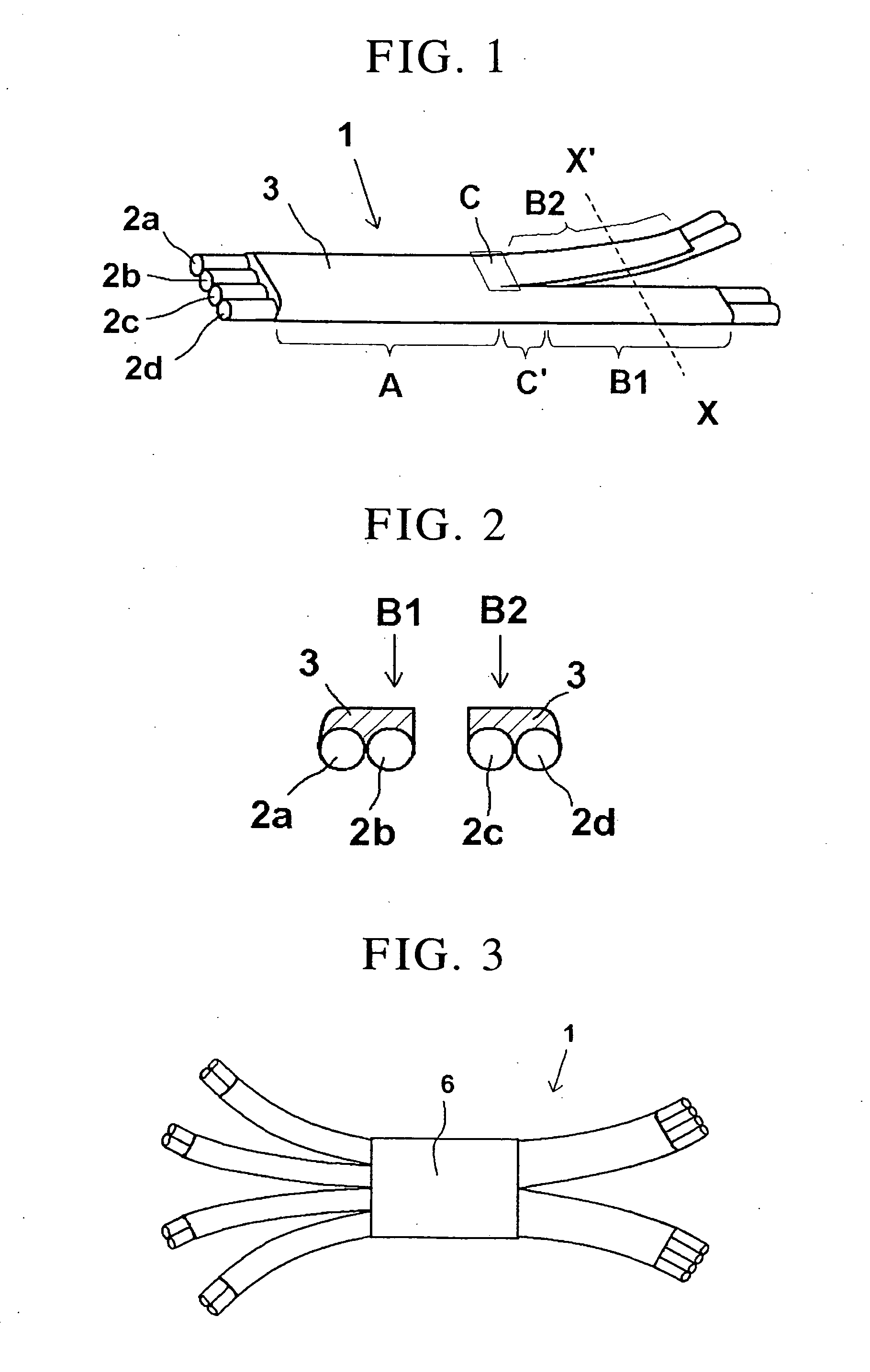
[0103] Eight 30-cm long coated optical fibers were aligned, and a covering material was applied to the coated optical fibers using the application apparatus in the same manner as in Example 1. The obtained assembly was held still for one hour in room temperature to cure the covering material to obtain a covering layer. Next, a 2-cm strip at the center of the optical fiber wiring sheet was covered with UV setting resin to a thickness of 2 mm, after which the UV setting resin was irradiated by a UV lamp for 2 minutes at an irradiation intensity of 20 mW / cm2 to cure the resin. Thereafter, the optical fibers were separated from the substrate, a covering material was formed, and then the covering material was completely cured in room temperature. Furthermore, clear resin was applied to the center part as a protective member (6) to form a covering layer, as shown in FIG. 3. Thereafter, the ends of four bundles each consisting of two coated optical fibers were held separately on one end of...

example 3

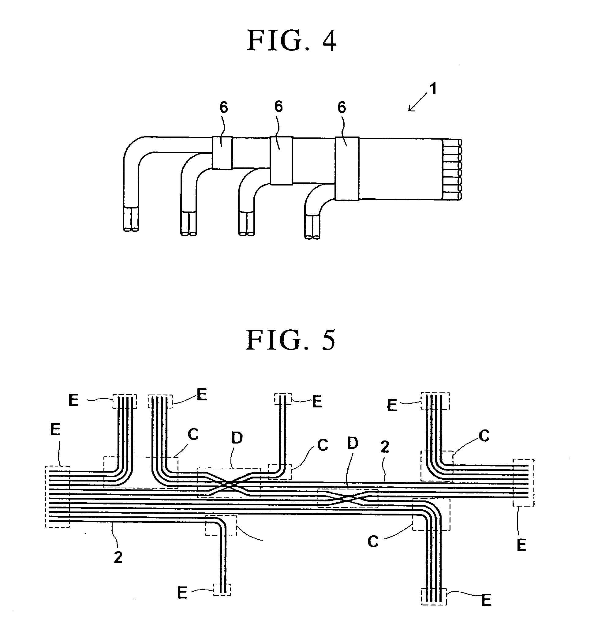
[0104] Eight 50-cm long coated optical fibers were aligned, and a covering material was applied to the entire coated optical fibers in the same manner as in Example 1 to form a covering layer. Next, a heat-shrinkable tube with slit (length: 2 cm) was placed, as a protective member (6), at the branching position of the coated optical fibers, and then the tube was shrunk using a heater. Thereafter, the coated optical fibers were branched into four bundles of two coated optical fibers each at intervals of 5 cm. This produced a fan-out optical fiber wiring sheet with its eight cores branching in sets of two cores at constant intervals, as shown in FIG. 4.


PUM


Abstract

An optical fiber wiring sheet includes: at least one optical-fiber aligning section including a plurality of two-dimensionally aligned and wired coated optical fibers; and at least one optical-fiber branching part where at least one of the plurality of coated optical fibers branches off as a branching coated optical fiber from the remaining coated optical fibers. The coated optical fibers have ends which constitute optical input / output ports.

Description

CROSS-REFERENCE TO RELATED APPLICATIONS [0001] This is a continuation of U.S. patent application Ser. No. 11 / 259,230, filed Oct. 26, 2005, which claims priority to Japanese Patent Application No. 2004-313003, filed Oct. 27, 2004, No. 2004-362162, filed Dec. 15, 2004, and No. 2005-094176, filed Mar. 29, 2005, and the disclosure of which is herein incorporated by reference in its entirety.BACKGROUND OF THE INVENTION [0002] 1. Field of the Invention [0003] The present invention relates to an optical fiber wiring sheet having a structure of branching coated optical fibers and used for optical circuit packages, optical circuit devices and other applications pertaining to optical communication and optical information processing, as well as a method of manufacturing the same. [0004] 2. Description of the Related Art [0005] As optical fiber wiring sheets that bundle coated optical fibers, optical fiber tape cores have been known. Just like optical fiber cables, etc., optical fiber tape core...

Claims


Application Information

Patent Timeline
Patent Type & Authority Applications(United States)
IPC IPC(8): G02B6/44
CPCG02B6/4403G02B6/4472G02B6/02395G02B6/4482
Inventor SASAKI, KYOICHISUZUKI, MASAYOSHIKOBAYASHI, TATSUSHISUKEGAWA, KEN
Owner SASAKI KYOICHI
Why Eureka
Try Eureka