
Packaging and application device with adjustable wiping

a technology of application device and wiping member, which is applied in the direction of packaging goods, brushes, applications, etc., can solve the problems of reducing the performance of the wiping member, reducing the elasticity non-uniform wiping of the application element, so as to facilitate the deformation of the deformable portion, facilitate the wiping, and deform relatively easily

Active Publication Date: 2007-06-21
LOREAL SA
View PDF10 Cites 8 Cited by
  • Summary
  • Abstract
  • Description
  • Claims
  • Application Information

AI Technical Summary

Benefits of technology

[0014] The invention typically facilitates implementation of a device providing at least two degrees of wiping of the application element, for example, strong wiping and weak wiping, or medium wiping and strong or weak wiping.
[0020] By way of example, the adjustment member can be configured to be fixed in a removable manner on the container. The adjustment member can also be configured to be fixed in a removable manner on the gripping member, which can make it possible to fix the applicator on the container by means of the adjustment member. The adjustment member can be shaped or decorated to contribute towards the aesthetic quality of the device, for example by being made with a color different from that of the gripping member or of the container. Further, the adjustment member can comprise an internally threaded mounting skirt, arranged to be screwed onto the container, and an externally threaded neck, onto which the gripping member can be screwed.
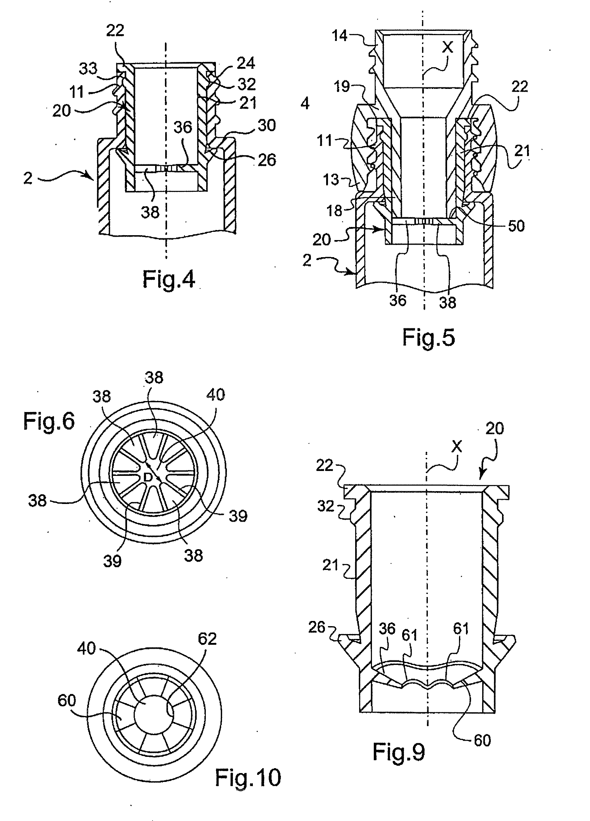
[0026] The deformable portion can extend substantially perpendicular to the axis of the rod at rest, or upwards or downwards relative to the axis of the rod in variants. The deformable portion of the wiping member can be implemented so as to be able to deform relatively easily, for example to spread without stretching. For example, the deformable portion of the wiping member can thus include, at least one slot, which can facilitate deformation of the deformable portion upon passage of the application element. The deformable portion can include one or more fins. The deformable portion can also comprise a corrugated lip.
[0027] The presence of at least one slot, fins or a corrugated lip can facilitate wiping a wide variety of application members, in particular application members having a cross-section relatively large compared with the cross-section of the rod and / or which are relatively fragile. For example, some application members include hairs or flocking.
[0028] The deformable portion of the wiping member can include at least one wiping lip with a radially internal free edge defining an opening for passage of the application element. The length of the perimeter of the free edge is typically greater than that of the opening observed in top projection. For example, by virtue of the presence of corrugations, the length of the perimeter of the free edge can be equal to the length of a perimeter of a larger opening without corrugations. The perimeter of the free edge is, in one example, greater in size than that of the rod intended to be wiped. The presence of corrugations allows the wiping lip to deform more easily upon passage of the application element when the latter is inserted into the container and / or extracted therefrom. The corrugations facilitate wiping the application element, and can reduce any piston (suction) effect created while wiping the rod.
[0030] In one example, the wiping member can include, at rest, an internal diameter close to that of the rod. In this example, when the application element is introduced through the wiping member, the corrugations of the wiping lip facilitate, by spreading, widening of the opening defined by the wiping lip in order to allow the application element to pass. One benefit of this arrangement is that excessive pressure liable to damage the wiping lip or application element is reduced. Accordingly, the wiping can remain gentle in the example discussed above, whereas a conventional wiping lip tends to become stiff upon widening.

Problems solved by technology

As the wiping member is made from an elastically deformable material, it risks losing elasticity by being kept under constraint during storage.
One drawback is that the passage area is not circular, which can lead to non-uniform wiping of the application element.
There is the risk, as for certain devices described in EP 0 002 301, of a reduction in performance of the wiping member in the event of prolonged storage under constraint.

Method used


Image

  • Packaging and application device with adjustable wiping
  • Packaging and application device with adjustable wiping
  • Packaging and application device with adjustable wiping

Examples


Embodiment Construction

[0056] Referring now to the drawings, wherein like reference numerals are used to designate identical or corresponding parts throughout the several views.

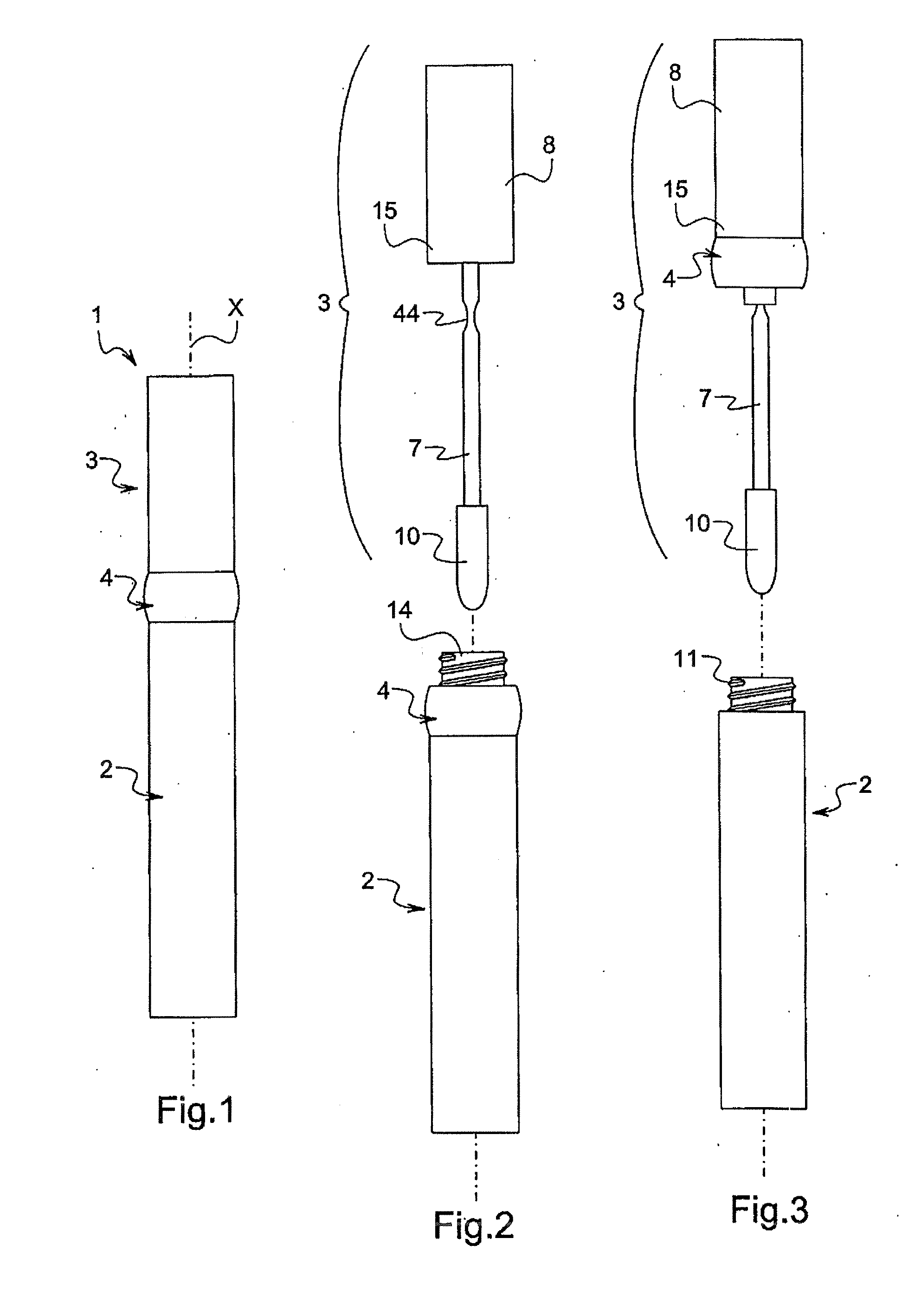
[0057]FIG. 1 depicts one example of a packaging and application device comprising a container 2 with longitudinal axis X and an applicator 3 capable of being separated from the container 2. The device 1 comprises a removable adjustment member 4, which allows fixing of the applicator 3 on the container 2. The applicator 3 includes a rod 7 which is connected at one end to a gripping member 8 and at the other end to an application element 10, which is, for example, a mascara brush.

[0058] In the example shown in FIG. 1, the container 2 includes a neck 11, threaded externally, and the adjustment member 4 includes, as can be seen in FIG. 5, a mounting skirt 13, threaded internally, arranged to be screwed onto the neck 11. The adjustment member 4 also includes an externally threaded neck 14, onto which an internally threaded mounting sk...


PUM


Abstract

The device includes a container and an applicator including a rod connected at a first end to a gripping member and to an application element at a second end. The device further includes a first wiping member disposed in the container and including a deformable portion configured to wipe the application element during extraction of the application element from the container. The device includes a movable adjustment member that limits deformation of the deformable portion during passage of the application element through the deformable portion. Deformation of the deformable portion is less limited by the adjustment member when the adjustment member is in a second position than when the adjustment member is in a first position. The adjustment member typically limits deformation of the deformable portion without substantially constraining the deformable portion when the deformable portion is un-deformed by either the application element or rod, irrespective of a position of the adjustment member.

Description

CROSS-REFERENCE TO RELATED APPLICATIONS [0001] This document claims priority to French Application Number 05 53900, filed Dec. 15, 2005, and U.S. Provisional Application No. 60 / 755,099, filed Jan. 3, 2006, the entire content of each of which are hereby incorporated by reference herein.FIELD OF THE INVENTION [0002] The present invention relates to packaging and application devices comprising a container containing the product to be applied and an applicator comprising a rod provided at an end with an application element. One example of the invention provides a device in which the application element is a brush or a comb for applying a make-up and / or care product on keratinous fibres, for example, the eyelashes and / or eyebrows. BACKGROUND OF THE INVENTION Discussion of Background [0003] EP 0 002 301 describes a device in which a container comprises a wiping member and an adjustment means making it possible to act on the size of the opening in the wiping member through which the applic...

Claims


Application Information

Patent Timeline
Patent Type & Authority Applications(United States)
IPC IPC(8): H01R12/00
CPCA45D34/047A45D40/268
Inventor GUERET, JEAN-LOUIS H.
Owner LOREAL SA
Learn More