Suture anchor device, kit and method

a technology of suture anchor and kit, which is applied in the field of suture, can solve the problems of no prior art showing a reel portion capable of providing an interference fit of suture between bone and anchorag

Inactive Publication Date: 2007-06-21
ARTHREX
View PDF55 Cites 45 Cited by
  • Summary
  • Abstract
  • Description
  • Claims
  • Application Information

AI Technical Summary

Problems solved by technology

None of the prior art shows a reel portion capable of providing an interference fit of suture between the bone and anchor.

Method used


Image

  • Suture anchor device, kit and method
  • Suture anchor device, kit and method
  • Suture anchor device, kit and method

Examples


Embodiment Construction

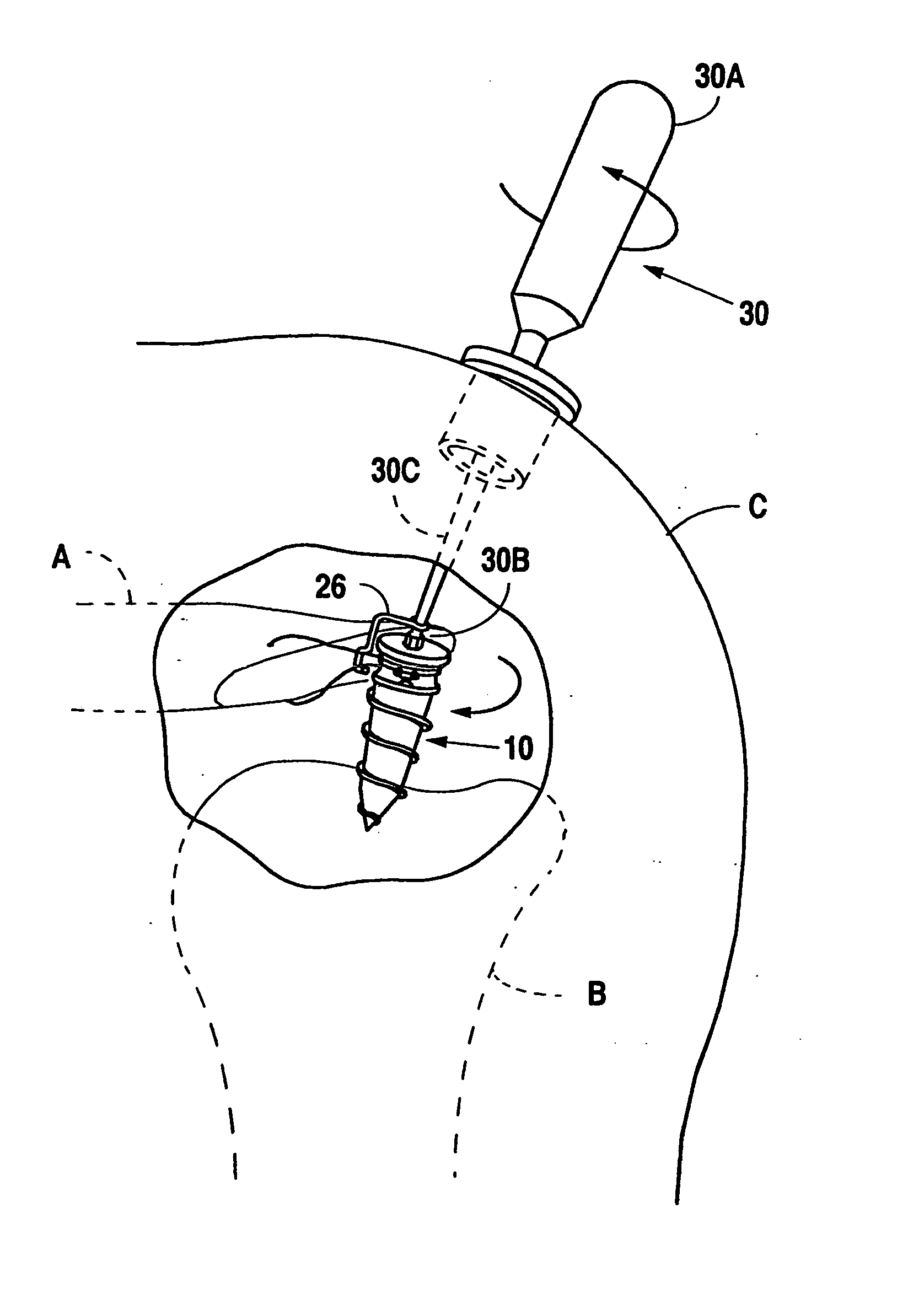
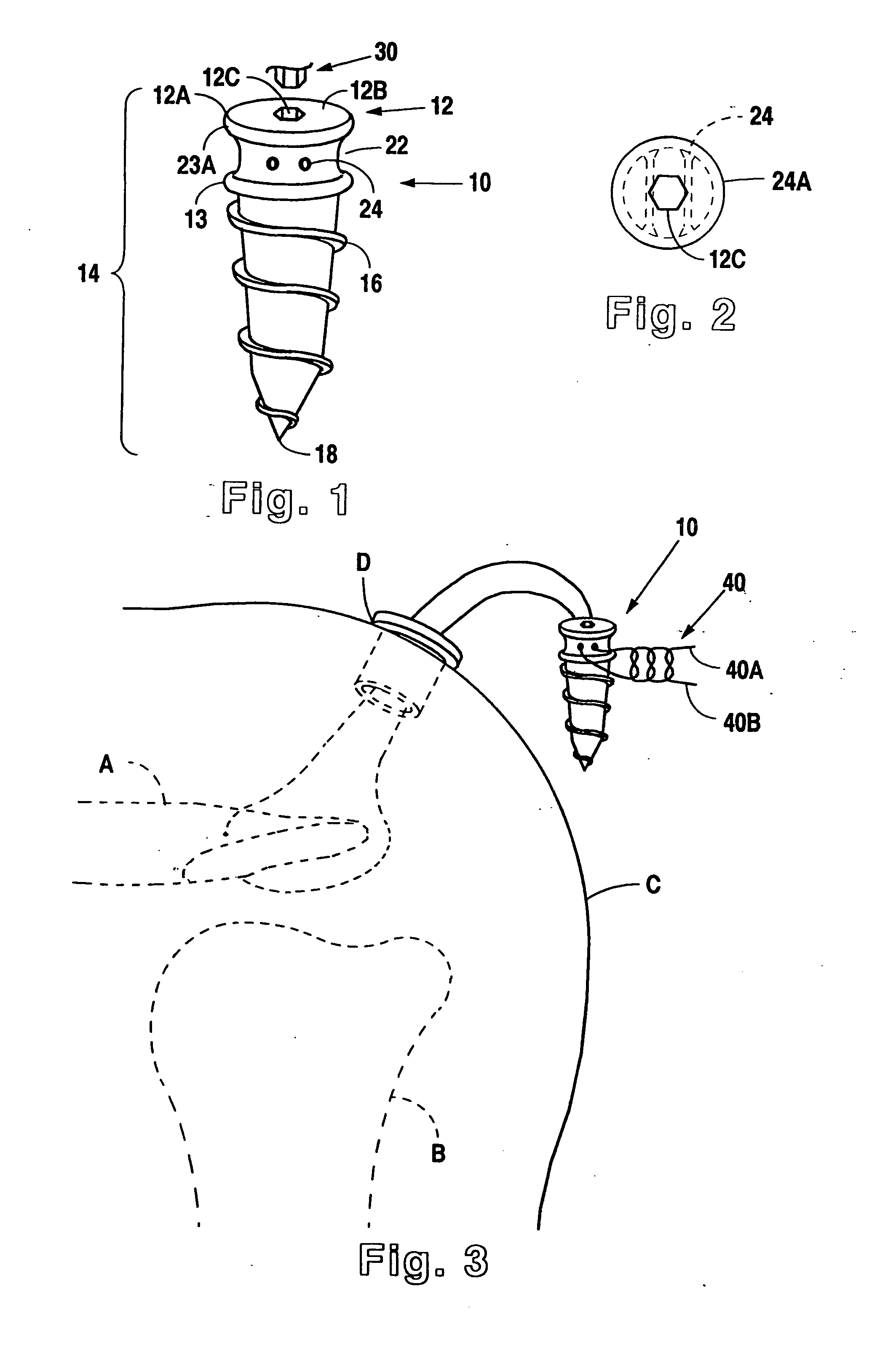
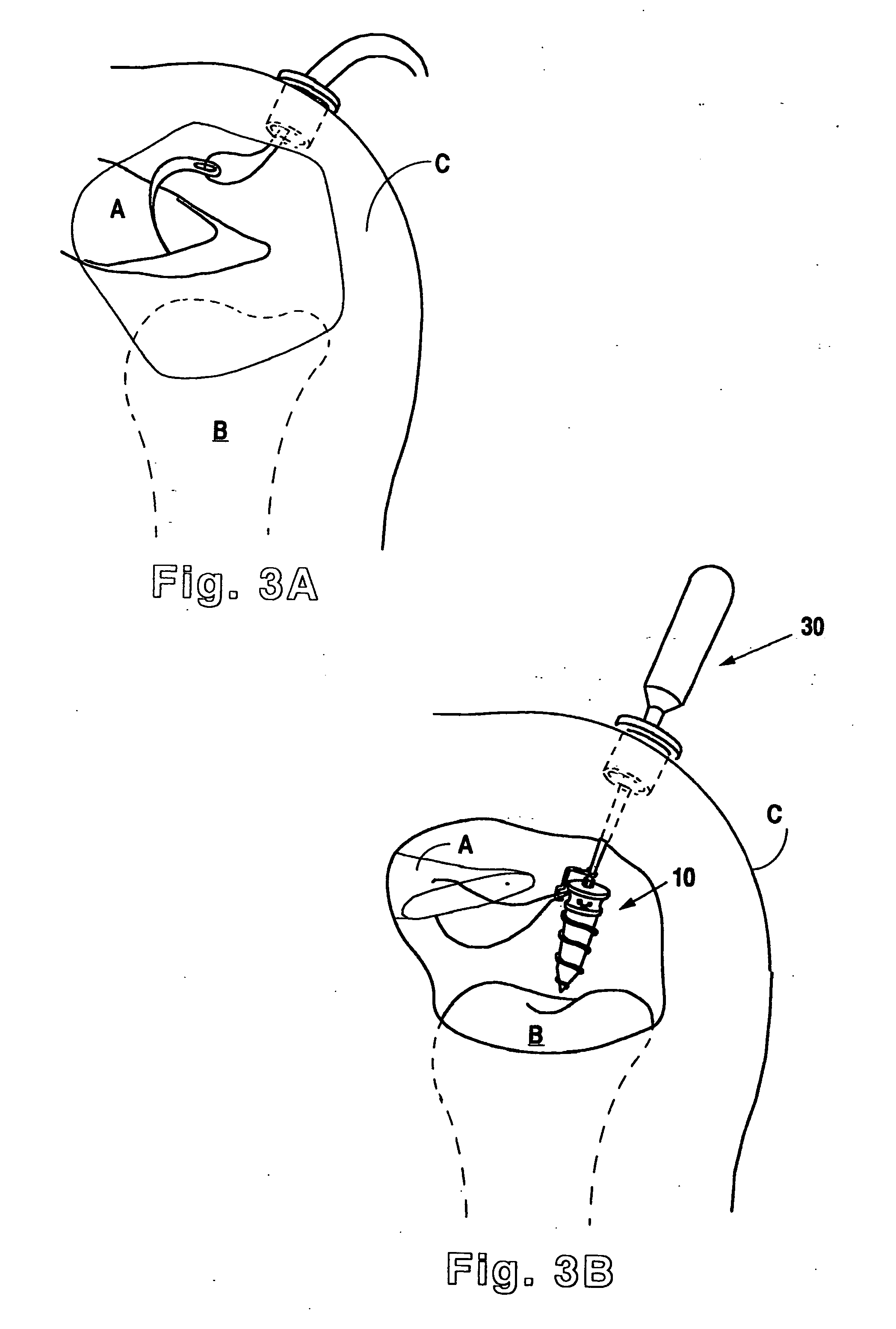
[0022] In viewing FIGS. 1 through 3 it is seen that Applicant's present invention includes a unitary, longitudinal suture anchor 10, typically made of titanium, stainless steel, plastic, allograft bone, or other suitable material, including a bio-absorbable material. The suture anchor is seen to have a generally circular head 12, the head typically having an outer edge 12A, an upper surface 12B, and walls 12C for engaging any type of mating tool as set forth in more detail below.

[0023] Applicant's novel suture anchor 10 includes a shank portion 14 located distal to the head 12, the shank portion 14 having threads 16 on at least a portion thereof, the shank portion 14 terminating at a tip 18. The shank portion 14 also includes a reel portion 22, typically having adjacent walls 23 defining a suture receiving portion. The particular configuration of the walls 23 here include a pair of holes 24 going from one portion of the outer surface of the shank portion 14 to a second portion of t...


PUM


Abstract

A suture anchor and kit for anchoring a suture member to human bone in an interference fit. A suture anchor includes a threaded portion and has a head at the proximal end thereof, the head being generally circular. A tip is located at a distal end of the shank. The shank is at least partially threaded and includes walls defining a reel portion. The shank also includes walls for engaging a suture, the walls for engaging the suture typically adjacent walls defining the reel portion. The head typically includes walls for engaging a drive tool. The kit includes a drive tool for rotating the suture anchor when a suture member is engaged with the walls for engaging the suture such that rotation of the anchor causes the suture material to wrap around the reel portion of the shank.

Description

[0001] This patent application is a continuation of and claims priority from U.S. patent application Ser. No. 10 / 412,205, filed Mar. 31, 2003; which is incorporated hereby by reference; and claims priority from U.S. Pat. No. 6,540,750, issued Apr. 1, 2003; and U.S. Pat. No. 6,267,766, issued Jul. 31, 2001.BACKGROUND OF THE INVENTION [0002] 1. Field of The Invention [0003] Applicant's invention relates to a device, method and kit for repairing tissue, namely for selectively positioning a suture-bearing tissue adjacent a bone mass. [0004] 2. Background Information [0005] When soft tissue, such as tendons and ligaments, are torn away from the bone, surgery may be required to repair the tear. Typically, a suture member is threaded through the torn tissue and through a tunnel drilled in the bone mass. The suture material is drawn up and tied so that the torn tissue lays adjacent the bone mass in proper position to heal. [0006] A number of assemblies have been provided to anchor tissue to...

Claims


Application Information

Patent Timeline
Patent Type & Authority Applications(United States)
IPC IPC(8): A61B17/04
CPCA61B17/0401A61B17/0485A61B2017/0409A61B2017/0459A61B2017/0414A61B2017/044A61B2017/0412
Inventor BURKHART, STEPHEN S.
Owner ARTHREX
Why Eureka
Try Eureka