Method and sensor arrangement for load measurement on rolling element bearing based on model deformation

a technology of rolling element bearings and sensor arrangements, applied in the direction of force sensors, instruments, force/torque/work measurement apparatus, etc., can solve the problems of insufficient general sense determination of load on the bearing by the relative straightforward vibration measurement method using the ball pass frequency, and achieve the effect of improving the quality of the measurement results

Active Publication Date: 2007-06-21
AB SKF
View PDF3 Cites 16 Cited by
  • Summary
  • Abstract
  • Description
  • Claims
  • Application Information

AI Technical Summary

Benefits of technology

[0010] To further improve the measurement result quality, N / 2 Chebyshev polynomial coefficients are determined from the sensor signals, representing at least one axial mode shape of the ring shaped element.

Problems solved by technology

However, this known sensor arrangement is not capable of measuring the total load vector applied to the bearing.
Also, due to the non-linear nature of a bearing, a relative straightforward vibration measurement method using the ball pass frequency is not sufficient to determine the loading on the bearing in a general sense.

Method used


Image

  • Method and sensor arrangement for load measurement on rolling element bearing based on model deformation
  • Method and sensor arrangement for load measurement on rolling element bearing based on model deformation
  • Method and sensor arrangement for load measurement on rolling element bearing based on model deformation

Examples


Embodiment Construction

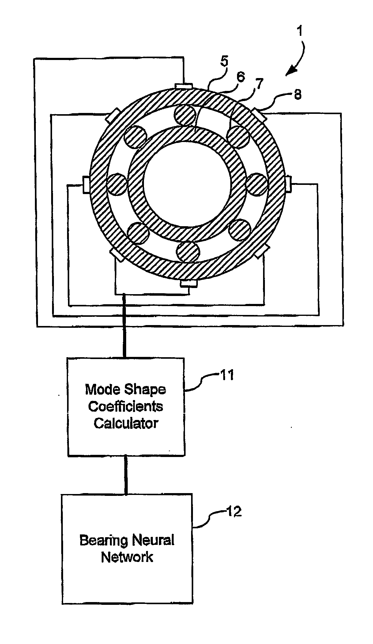
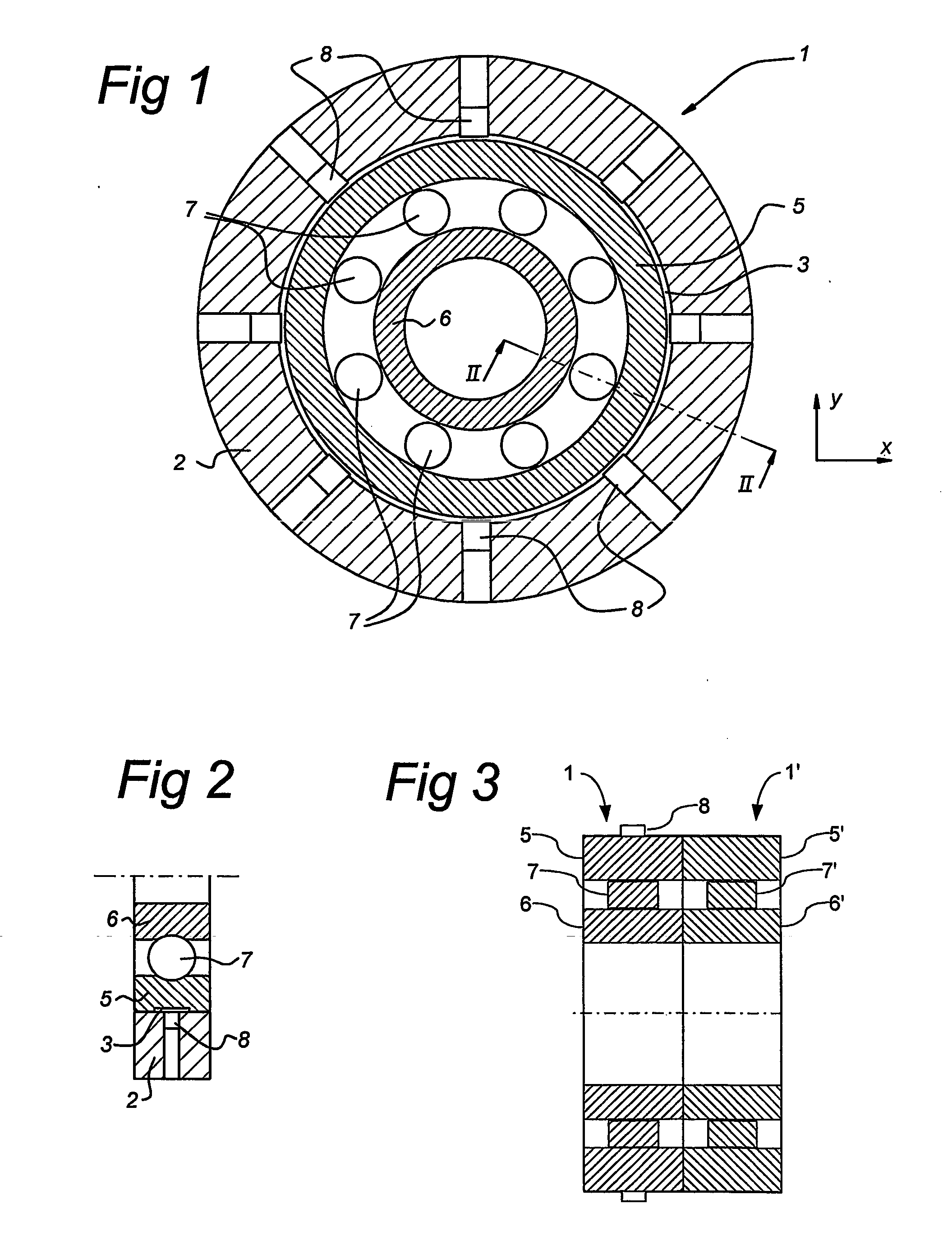
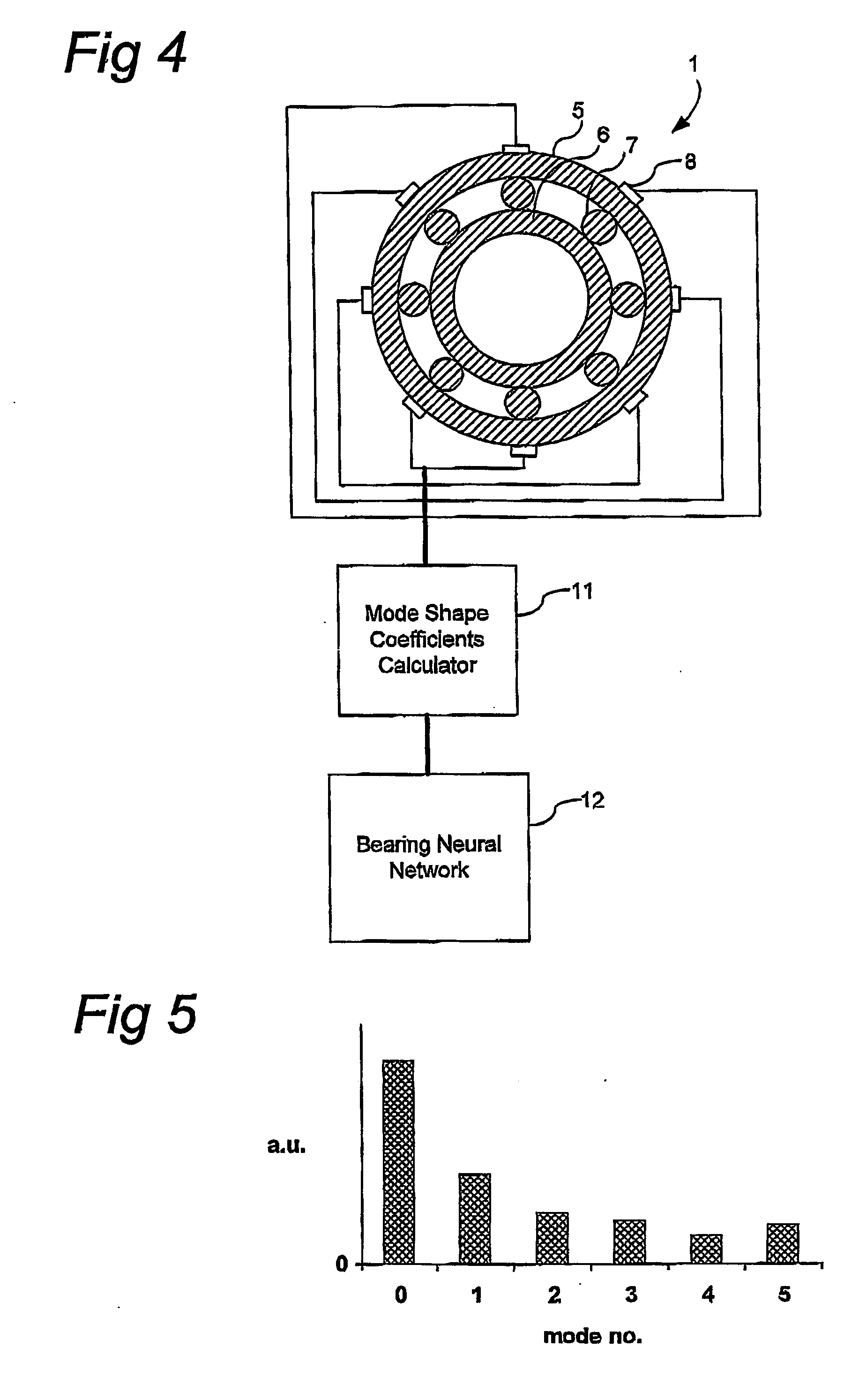
[0017] In FIG. 1 a cross sectional view is shown of a rolling element bearing 1, e.g. a ball bearing or roller bearing. The rolling element bearing 1 comprises an outer ring 5, an inner ring 6 and a number of rolling elements 7, such as balls or rollers (the number of rolling elements 7 being eight in the drawing). The outer ring 5 of the rolling element bearing 1 is fixed in a sensor holder 2, which forms the fixed world for the rolling element bearing 1. In the sensor holder 2 eight sensors 8 are provided at locations facing the bearing outer ring 5 with (angular) spacing corresponding to the angular spacing of the rolling elements 7 of the bearing 1. The sensors 8 may e.g. be displacement sensors or vibration sensors, known as such to the person skilled in the art.

[0018] As shown in the cross sectional view of FIG. 2, the bearing outer ring 5 is provided with a recession 3 at its outer periphery. The outer surfaces of the bearing outer ring 5 are in close contact with the sensor...


PUM

PropertyMeasurementUnit
displacementaaaaaaaaaa
mode shape coefficients calculatoraaaaaaaaaa
mode shape coefficientaaaaaaaaaa

Abstract

Method and sensor arrangement for determining a load vector acting on a rolling element bearing (1) in operation. A plurality of N sensors (8) are provided which measure displacement and/or strain for determining displacement and/or strain in one of the elements (5, 6, 7) of the rolling element bearing (1). Furthermore, a mode shape coefficients calculator (11) is provided, connected to the plurality of N sensors (8), for determining a deformation of the element (5, 6, 7) by calculating amplitude and phase of N/2 Fourier terms representing at least one radial mode shape of the ring shape element (5, 6, 7). Also, a bearing neural network (12) is present, connected to the mode shape coefficients calculator (11), the bearing neural network (12) being trained to provide the load vector on the rolling element bearing (1) from the N/2 Fourier terms.

Description

FIELD OF THE INVENTION [0001] The present invention relates to load measurements on rolling element bearings, such as ball bearings or roller bearings. More specifically, the present invention relates to a method and sensor arrangement for determining a load vector acting on a rolling element bearing, comprising measuring displacement and / or strain using N sensors for determining displacement and / or strain in a ring shaped element of the rolling element bearing. PRIOR ART [0002] Such a load measuring method and sensor arrangement are e.g. known from American patent U.S. Pat. No. 5,140,849, which describes a rolling element bearing with a sensor unit. The sensor unit comprises two sensor elements, in the form of strain gauges, which effectively measure a number of performance characteristics of the bearing, including the applied load, rotational speed and acceleration. [0003] However, this known sensor arrangement is not capable of measuring the total load vector applied to the beari...

Claims


Application Information

Patent Timeline
Patent Type & Authority Applications(United States)
IPC IPC(8): G01L1/00G01L5/00
CPCF16C19/52G01L5/0009G01M13/045F16C19/522F16C2233/00G01L5/00
Inventor MOL, HENDRIK ANNE
Owner AB SKF
Why Eureka
Try Eureka