Ventilator adaptable for use with either a dual-limb circuit or a single-limb circuit

Active Publication Date: 2007-06-28
PHILIPS RS NORTH AMERICA LLC
View PDF19 Cites 60 Cited by
  • Summary
  • Abstract
  • Description
  • Claims
  • Application Information

AI Technical Summary

Benefits of technology

[0011] Accordingly, it is an object of the present invention to provide a ventilator that overcomes the shortcomings of conventional ventilators. This object is achieved according to one embodiment of the present invention by providing a ventilator that includes a housing, a gas flow generator disposed in the housing, a gas outlet port disposed on an exterior surface of the housing, a first conduit coupling the gas flow generator to the gas outlet port, a gas inlet port disposed on an exterior surface of the housing, a first exhaust valve disposed in the housing, and a second conduit coupling the gas inlet port to the first exhaust valve. The first exhaust valve controls a flow of exhaust gas from the second conduit. A second exhaust valve is disposed in the housing and is

Problems solved by technology

In a single-limb ventilator system, there is a known leak from the system through the exhaust port as well as potential unknown leaks, such as leaks at the mask/patient interface.
Thus, dual-limb ventilator systems are not leak tolerant as they do not have the ability to account for leaks.
Conversely, dual-limb ventilator systems are not well suited to situations where non-invasive ventilation is desired, because of their inability to handle leaks, which are common when ventilating a patient non-invasively.
However, this dual-limb configuration is disadvantageous because the

Method used


Image

  • Ventilator adaptable for use with either a dual-limb circuit or a single-limb circuit
  • Ventilator adaptable for use with either a dual-limb circuit or a single-limb circuit
  • Ventilator adaptable for use with either a dual-limb circuit or a single-limb circuit

Examples


Embodiment Construction

[0020] Directional phrases used herein, such as, for example, left, right, clockwise, counterclockwise, top, bottom, up, down, and derivatives thereof, relate to the orientation of the elements shown in the drawings and are not limiting upon the claims unless expressly recited therein.

[0021] As employed herein, the term “number” shall mean one or more than one and the singular form of “a”, “an”, and “the” include plural referents unless the context clearly indicates otherwise.

[0022] As employed herein, the statement that two or more parts are “connected” or “coupled” together shall mean that the parts are joined together either directly or joined together through one or more intermediate parts. Further, as employed herein, the statement that two or more parts are “attached” together shall mean that the parts are joined together directly.

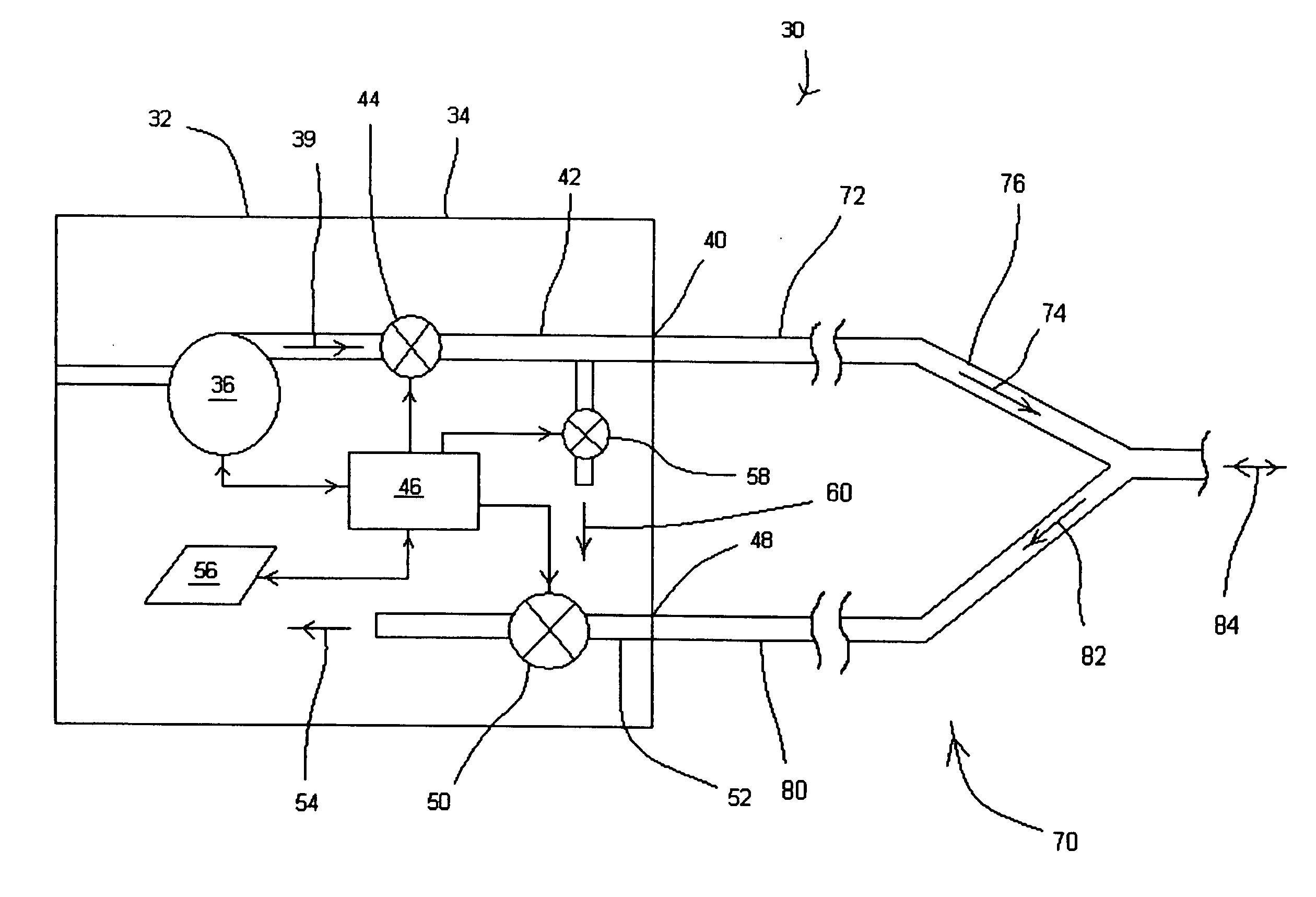
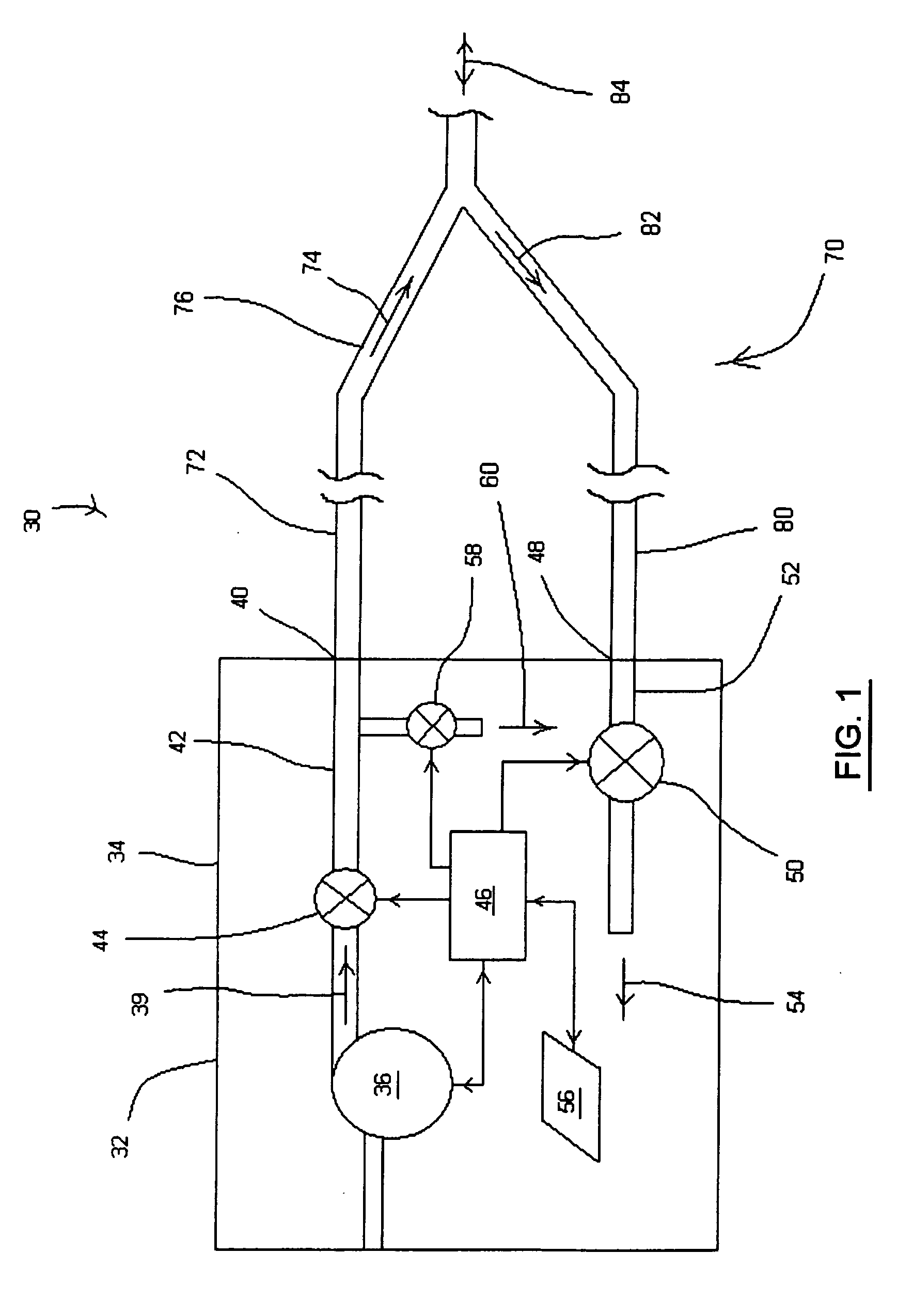
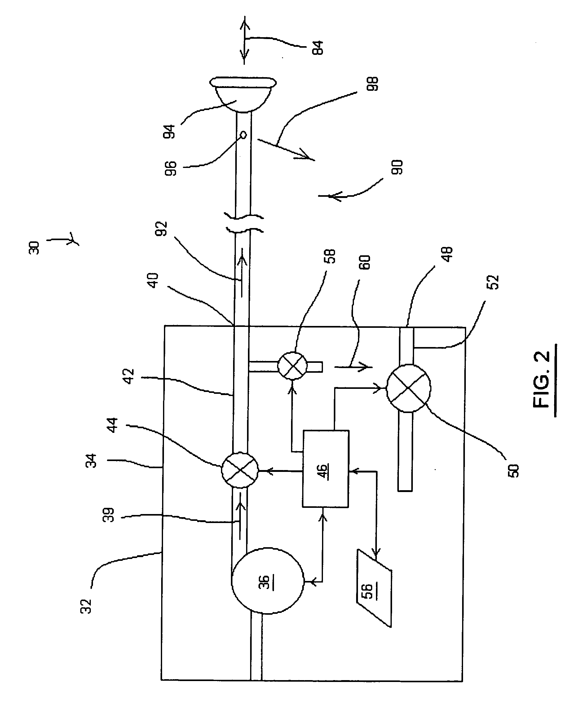
[0023]FIGS. 1 and 2 schematically illustrate an exemplary embodiment of a ventilation system, generally indicated at 30, that includes a ventilat...


PUM


Abstract

A ventilator of the present invention includes a housing, a gas flow generator disposed in the housing, a gas outlet port provided on an exterior surface of the housing, and a first conduit coupling the gas flow generator to the gas outlet port. A gas inlet port is also provided on an exterior surface of the housing. A second conduit couples the gas inlet port to a first exhaust valve in the housing that regulates a flow of exhaust gas from the second conduit. A second exhaust valve in the housing is coupled to the first conduit and regulates a flow of exhaust gas from the first conduit. A controller coupled to second exhaust valve causes the second exhaust valve to change a degree of flow restriction based on a respiratory phase of a patient coupled to the ventilator when the ventilator is operating in a single-limb ventilation configuration.

Description

BACKGROUND OF THE INVENTION [0001] 1. Field of the Invention [0002] The present invention pertains to a system and method for ventilating a patient that allows a ventilator to be connected to the airway of a patient using either a single-limb breathing circuit or a dual-limb breathing circuit to optimize the flexibility of the ventilator and treatment options available for the patient. [0003] 2. Description of the Related Art [0004] It is known to provide pressure support to a patient through a single-limb breathing circuit and a patient interface. Such ventilation systems typically generate a flow of gas using, for example, a blower. The pressure or flow of gas delivered to the patient is controlled by controlling the operating speed of the blower, controlling a valve that diverts gas from the gas flow path, or a combination thereof. The gas flow is communicated to the airway of the patient by means of the breathing circuit, which is usually a flexible tube coupled to a gas outlet ...

Claims


Application Information

Patent Timeline
IPC IPC(8): A61M16/00A62B9/02
CPCA61M16/00A61M2205/3553A61M2205/3584A62B9/02A61M16/0883A61M16/0066A61M2016/0015A61M2016/0027A61M16/101A61M16/0858A61M16/024
Inventor DOYLE, PETER R.
Owner PHILIPS RS NORTH AMERICA LLC
Why Eureka
Try Eureka