

Heat exchanger
- Summary
- Abstract
- Description
- Claims
- Application Information
AI Technical Summary
Benefits of technology
Problems solved by technology
Method used
Image

Examples
Embodiment Construction
[0034] An embodiment of the present invention is now explained in reference to the drawings.
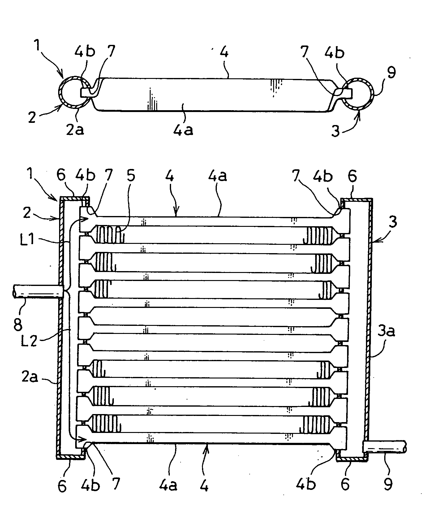
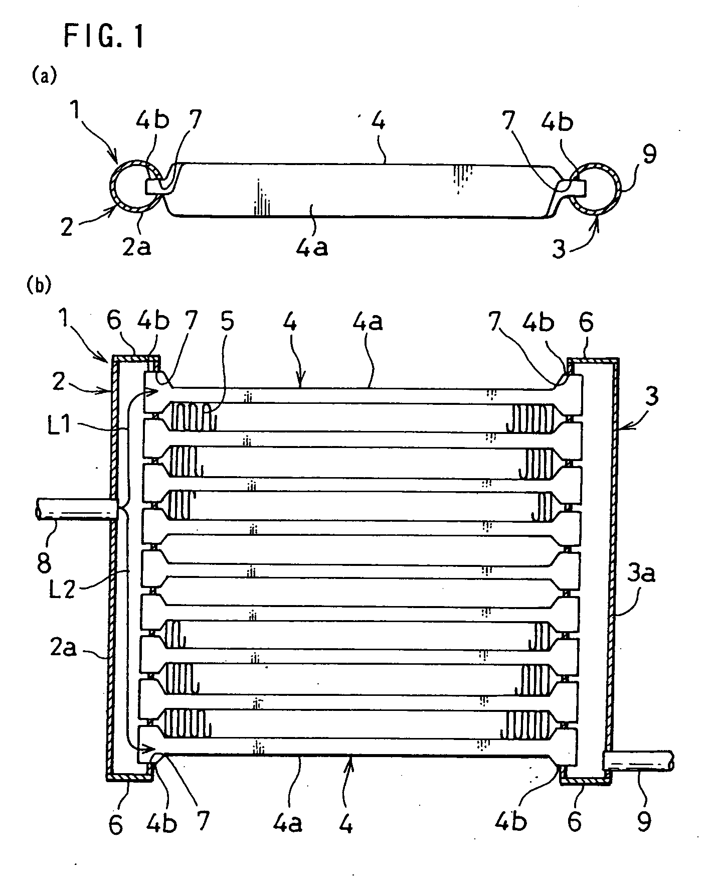
[0035] A heat exchanger 1 shown in FIGS. 1 through 4 may be used as a condenser constituting part of a refrigerating cycle in, for instance, an automotive air-conditioning system, in which a high-pressure coolant such as CO2 is used. The heat exchanger 1 includes a pair of tanks 2 and 3, a plurality of tubes 4 communicating between the pair of tanks 2 and 3 and corrugated fins 5 inserted and bonded between the tubes 4. In the heat exchanger 1 adopting a standard structure, the tanks 2 and 3 are disposed so as to range from top to bottom as shown in FIG. 1(b) and thus, air flowing perpendicular to the drawing sheet passes through the fins 5.
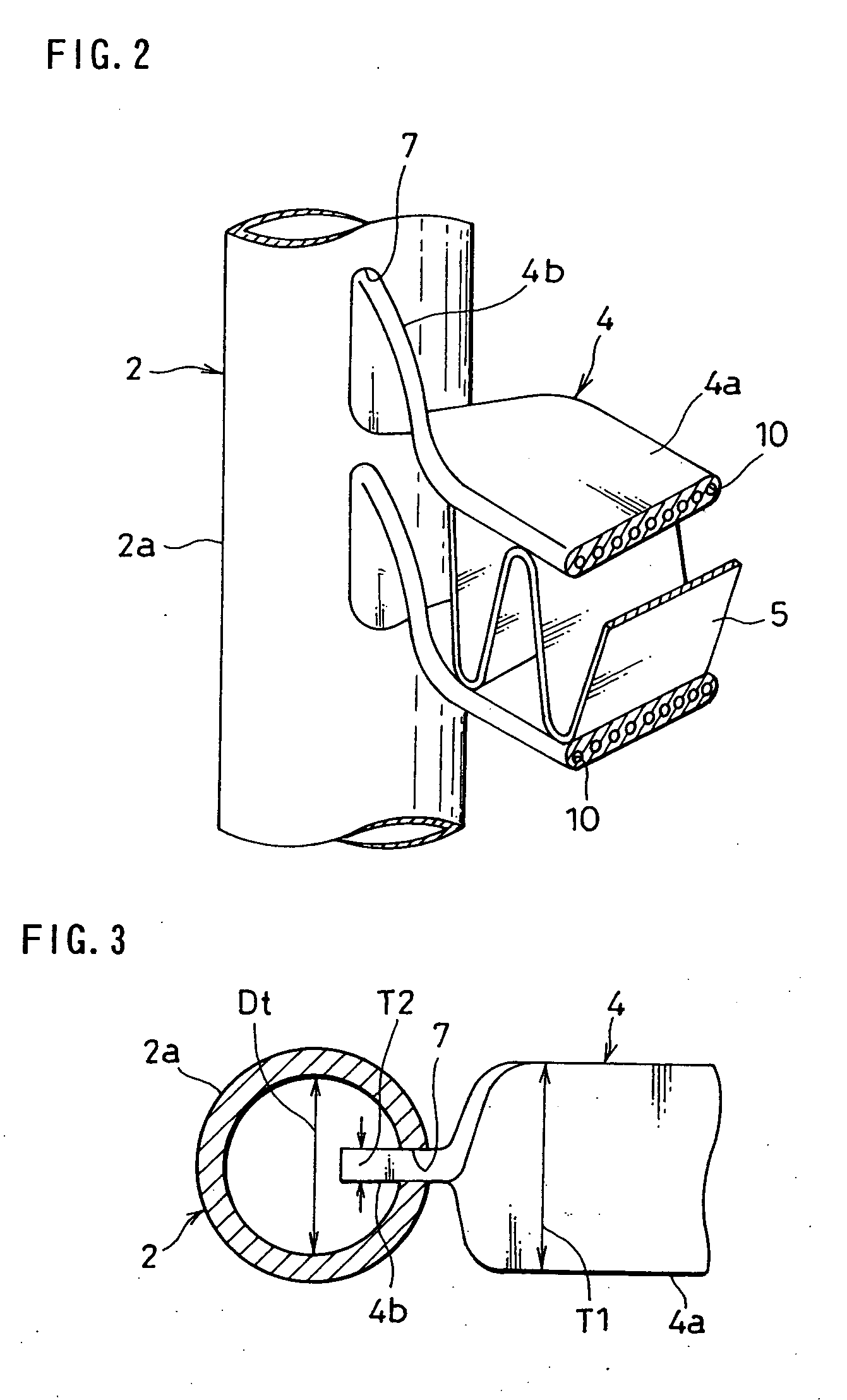
[0036] The tanks 2 and 3 respectively include header main units 2a and 3a formed by extruding an aluminum material clad with a brazing material into tubular shapes with the openings at the ends of the header main units 2a and 3a on the two sides closed of...
PUM
 Abstract
Description
Claims
Application Information