Lubrication device for machine tools

a technology for lubricating devices and machine tools, which is applied in the direction of engine components, boring/drilling components, packaging, etc., can solve the problems of high production cost, affecting the cost of finished workpieces, and machining tim

Inactive Publication Date: 2007-06-28
DROPSA
View PDF17 Cites 11 Cited by
  • Summary
  • Abstract
  • Description
  • Claims
  • Application Information

AI Technical Summary

Benefits of technology

[0010]The technical aim of the present invention is therefore to provide a lubrication devic

Problems solved by technology

However, numerous machine tool operations (for example chip removal operations) require lubrication of that part of the workpiece to be machined.
This procedure clearly presents numerous drawbacks, including in particular a considerable mach

Method used


Image

  • Lubrication device for machine tools
  • Lubrication device for machine tools
  • Lubrication device for machine tools

Examples


Embodiment Construction

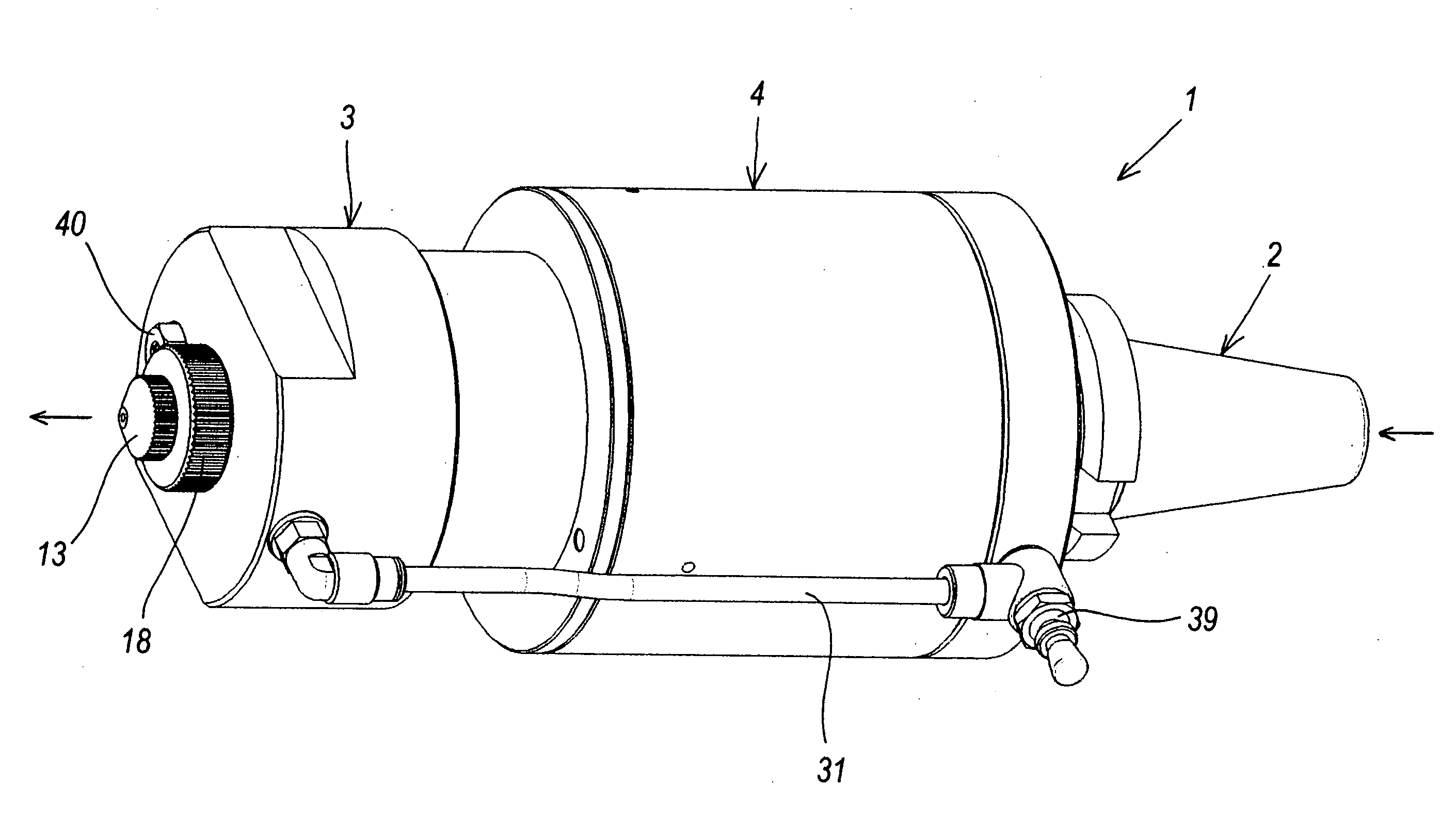
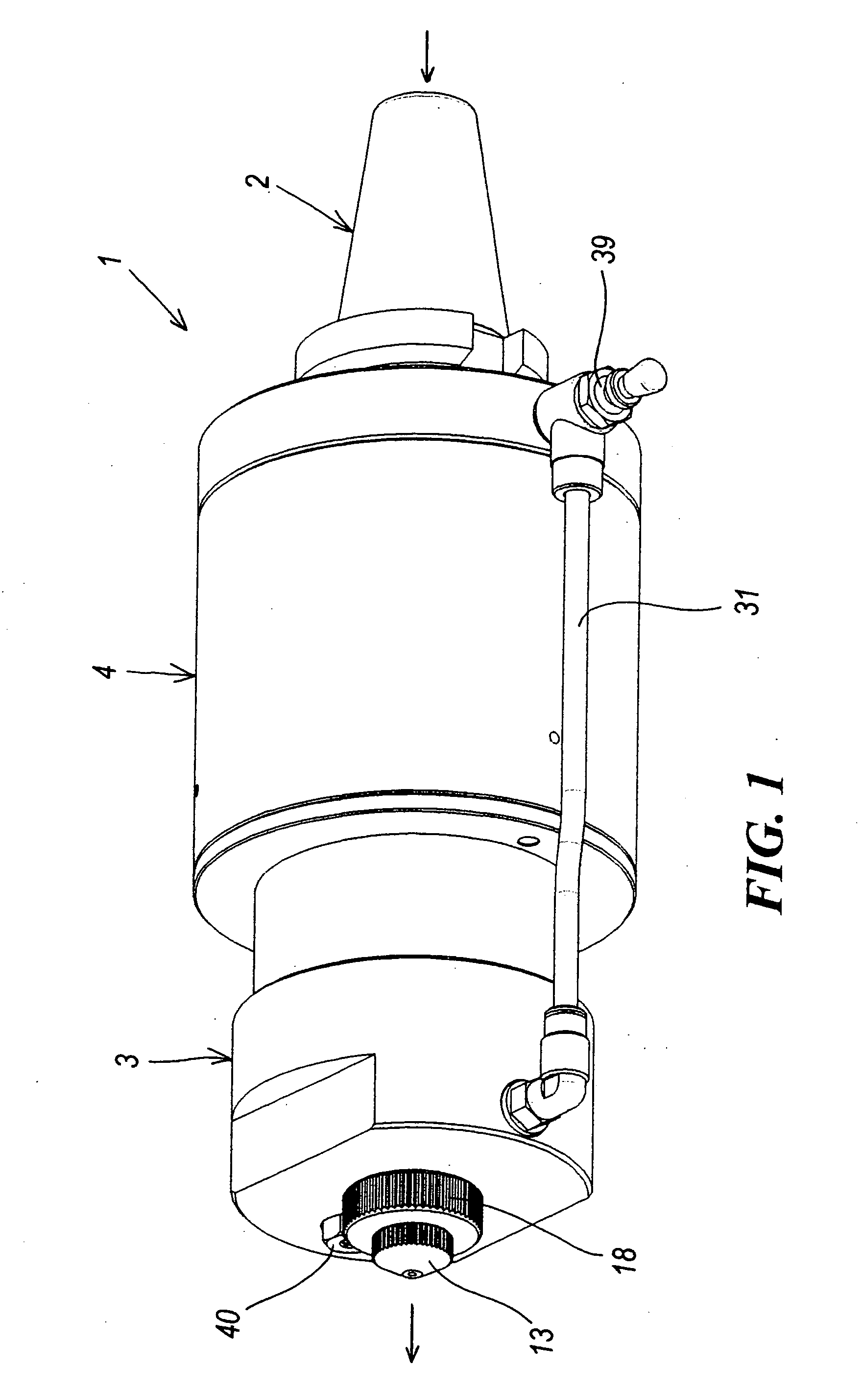
[0019]With reference to said figures, these show a machine tool lubrication device indicated overall by the reference numeral 1.

[0020]The device 1 comprises connection means 2 automatically grippable by a manipulator of the machine tool, lubricant dispensing means 3 and dispensing control means 4 activated by the machine tool itself.

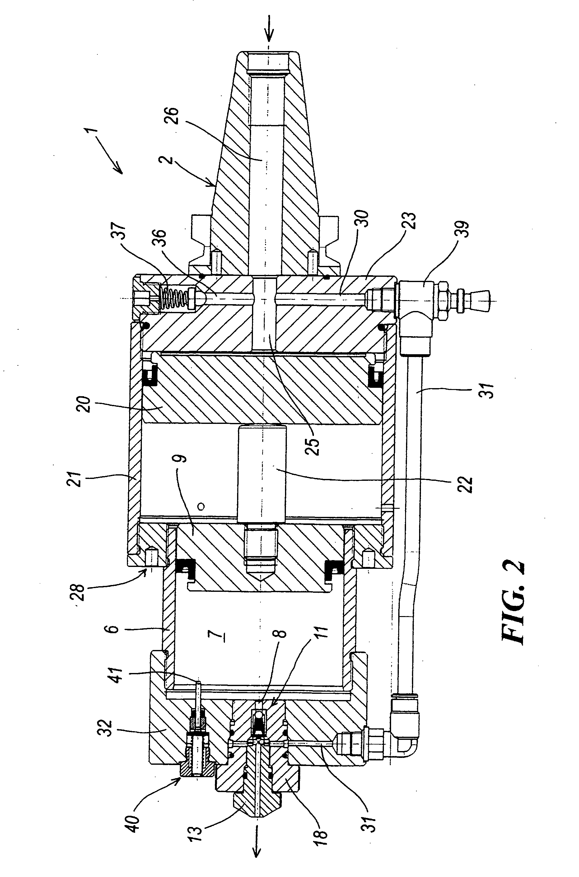
[0021]Specifically, the dispensing means 3 comprise a pump formed by a dispensing cylinder 6 defining a dispensing chamber 7 and provided with a lubricant exit orifice 8.

[0022]A dispensing piston 9 slides in the interior of the dispensing cylinder 6 to dispense lubricant from the orifice 8.

[0023]Preferably, at the orifice 8 the device 1 presents a non-return valve 11 provided with regulating means for the opening pressure, such that the valve 11 opens only when the piston 9 (by translating) raises the pressure in the chamber 7 to a value higher than a minimum value.

[0024]These regulating means for the opening pressure of the non-return valve 11 comprise ...


PUM

PropertyMeasurementUnit
Pressureaaaaaaaaaa
Transparencyaaaaaaaaaa

Abstract

The machine tool lubrication device comprises connection means grippable automatically by a manipulator of the machine tool, lubricant dispensing means, and dispensing control means operable by the machine tool.

Description

BACKGROUND OF THE INVENTION [0001]1. Field of the Invention[0002]The present invention relates to a lubrication device for machine tools.[0003]Machine tools are currently structured as machining centres and present one or more spindles on which a tool housed in a tool magazine is automatically mounted (depending on the particular operation to be carried out).[0004]2. Discussion of the Related Art[0005]However, numerous machine tool operations (for example chip removal operations) require lubrication of that part of the workpiece to be machined.[0006]In these cases the machine tool is opened and, using a droplet feeder or similar device, a few oil droplets are deposited on that part of the workpiece to be machined.[0007]The machine tool is then closed and machining commences.[0008]This procedure clearly presents numerous drawbacks, including in particular a considerable machining time due to the need to operate manually by opening the machine and lubricating the workpiece.[0009]The c...

Claims


Application Information

Patent Timeline
IPC IPC(8): B67D1/08
CPCB23Q11/10B23Q2230/002Y10T408/45Y10T408/453Y10T408/85884Y10T408/03B23Q11/1023B23Q11/1084
Inventor DIVISI, WALTER
Owner DROPSA
Why Eureka
Try Eureka