Patio umbrella and table set frame assembly

Inactive Publication Date: 2007-06-28
FISCHER MICHAEL S
View PDF9 Cites 12 Cited by
  • Summary
  • Abstract
  • Description
  • Claims
  • Application Information

AI Technical Summary

Benefits of technology

[0010]A patio set embodying the present invention is capable of being used with varying sized and shaped balconies in that the unit does not protrude more than approximately 1.5 inches beyond the balcony edge, thereby allowing it to be used with both large and small balconies.
[0011]Another object of the present invention is found in a patio set embodying the present invention that provides for safety, as the inventive structure makes it virtually impossible for any patio set part or piece, such as a nut, bolt, screw, etc to fall off from the balcony, as all such components are located away from the balcony edge, thereby providing a safe environment for those below the balcony.
[0012]Yet another object of the present invention is found in a patio set embodying the present invention that provides for the safety of a user of the patio set in that a user of the patio set may easily and safely attach an umbrella to the patio set by having the umbrella pole slide into securing brackets without having to lift the umbrella up and over the balcony edge. This is a safety concern not met by many existing balcony patio sets, as umbrellas are both cumbersome to handle and may cause danger for the old or infirm who attempt to install umbrellas on patio sets especially in windy weather.
[0015]Upper and lower leveling and stabilizing plates are held spaced apart from their respective upper and lower horizontal brace members. Each of these plates has a compression knob threadably mating with its respective brace member and connects the compression plate with the brace member for varying the spacing therebetween. Tightening or loosening the compression knob moves the compression plate inward or outward from its brace member so that the leveling and stabilizing plates rest against the patio side wall or railing when the L-shaped frame members are fitted over the patio wall or railing, thereby allowing for adjustment to support the frame in a substantially vertical position.

Problems solved by technology

This is a safety concern not met by many existing balcony patio sets, as umbrellas are both cumbersome to handle and may cause danger for the old or infirm who attempt to install umbrellas on patio sets especially in windy weather.

Method used


Image

  • Patio umbrella and table set frame assembly
  • Patio umbrella and table set frame assembly
  • Patio umbrella and table set frame assembly

Examples


Embodiment Construction

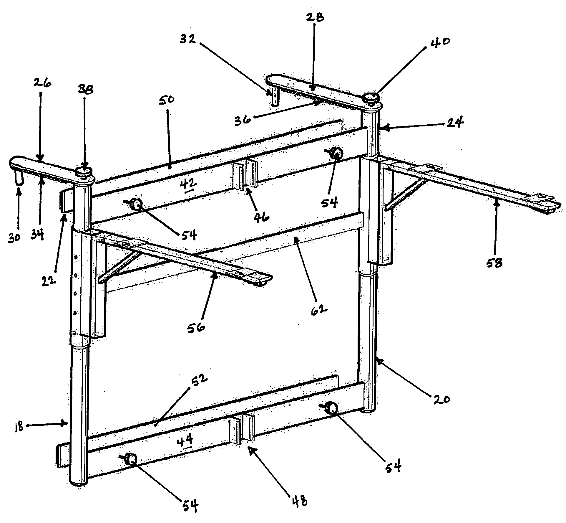
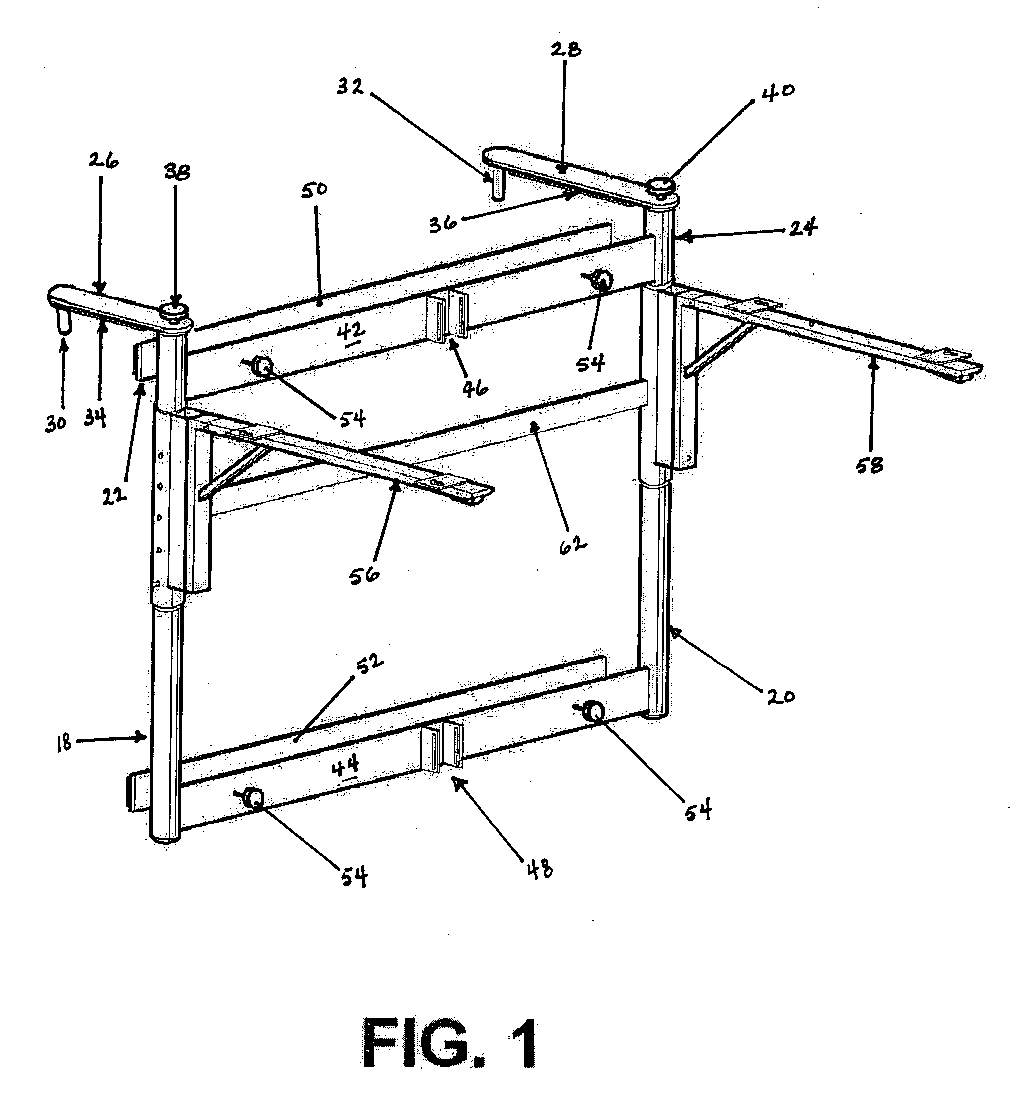
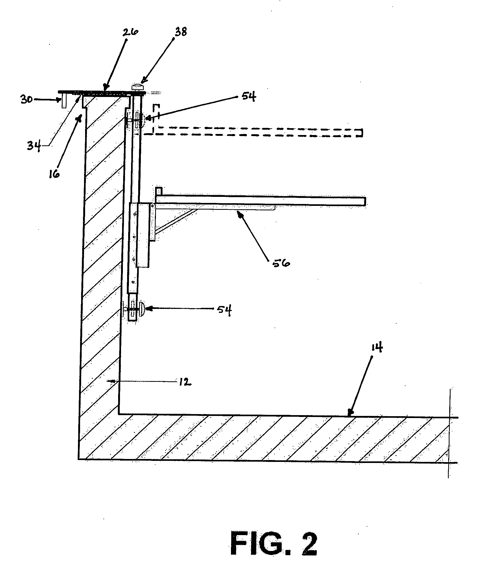
[0023]Referring now to the drawings, a hanging table and umbrella patio set hanger frame assembly for support upon a side wall or railing of a patio deck that embodies the present invention will be described.

[0024]A patio set hanger frame assembly 10 according to the invention attaches to a balcony 12 enclosing an outdoor deck 14. The balcony wall 12 has a horizontal top 16 as depicted in FIGS. 2, 4 and 5.

[0025]The present frame assembly 10 is designed for attachment to varying types of balcony walls and railings, including those balconies employing a railing which is wider at its top horizontal portion than at its vertical portion, thus providing a large overhang at the top of the balcony railing. A balcony with this type of railing does not easily accommodate the usual brackets and hangers that are commonly employed in the known patio set hanger frame assemblies and, for this reason, the known frame assemblies have not exhibited good stability and convenience in use.

[0026]In the p...


PUM


Abstract

The present invention discloses a hanging patio set frame assembly for supporting a table and an umbrella which can be quickly and easily attached to a balcony wall or railing in a removable manner. A vertical frame is hung from a balcony wall using swinging clamps and stabilized using telescoping compression plates. A table top is supported on the frame and provision is made on the frame for supporting the stick portion of a patio umbrella to provide shade for the user.

Description

FIELD OF THE INVENTION[0001]The present invention pertains to a hanging table and umbrella patio set hanger frame assembly for supporting a table and an umbrella which can be quickly and easily attached to a wall or railing in a removable manner. In an exemplary embodiment the support assembly is particularly adapted for use over a railing type structure. It should be appreciated however, that the assembly of the present invention may be attached to other structures such as a boat railing, porch railing, balcony railing, chain link fence railing, and over the tailgate of a pickup truck. It is also envisioned that the assembly of the present invention can also be attached to walls as well as to railings.BACKGROUND OF THE INVENTION[0002]The portable patio table and umbrella assembly of the invention differs from known patio table and umbrella assemblies in that it is designed to be both compact and movable on a patio by being supported on a patio wall or railing and is characterized b...

Claims


Application Information

Patent Timeline
IPC IPC(8): A47B96/06
CPCA47B37/04
Inventor FISCHER, MICHAEL S.
Owner FISCHER MICHAEL S
Why Eureka
Try Eureka