Security tag for cigarette pack

a technology for security tags and cigarettes, applied in the field of security tags, can solve the problems of increasing the complexity of the manufacturing machinery required for production, increasing the processing time and cost per unit, and wasting resources used in the first instance to form the security tag,

Inactive Publication Date: 2007-06-28
CHECKPOINT SYST INC
View PDF8 Cites 33 Cited by
  • Summary
  • Abstract
  • Description
  • Claims
  • Application Information

AI Technical Summary

Problems solved by technology

However, the application of the EAS or RFID security tag to the item or its packaging in the first instance can be expensive and wasteful of resources used to form the security tag.
However, such products utilize, and indeed require, substrates which use patterned sides of conductive material on both face surfaces of the substrate for proper operation.
For example, since special patterning and etching techniques must be utilized on both sides of the available tags to produce the proper circuit, per unit processing time and costs are increased.
Furthermore, the complexity of the manufacturing machinery required for production is also increased.
As may be appreciated, two sided photo-etching is generally time consuming and requires precise alignment of the patterns on both sides.
Additional material is also necessary to pattern both sides, thus increasing the per unit material costs.
Applying such EAS or RFID security tags to cigarette cartons, let alone to each cigarette pack can be expensive.
Moreover, the presence of the foil layer in each cigarette pack can distort or otherwise affect EAS or RFID security tag performance.

Method used


Image

  • Security tag for cigarette pack
  • Security tag for cigarette pack
  • Security tag for cigarette pack

Examples


embodiment 22

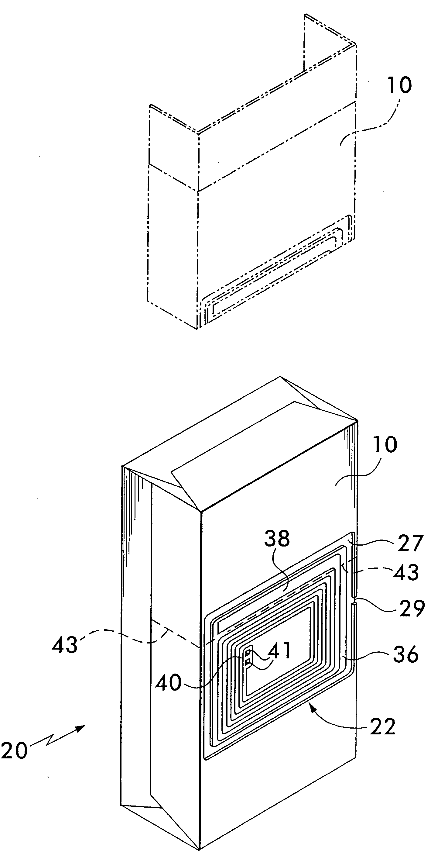
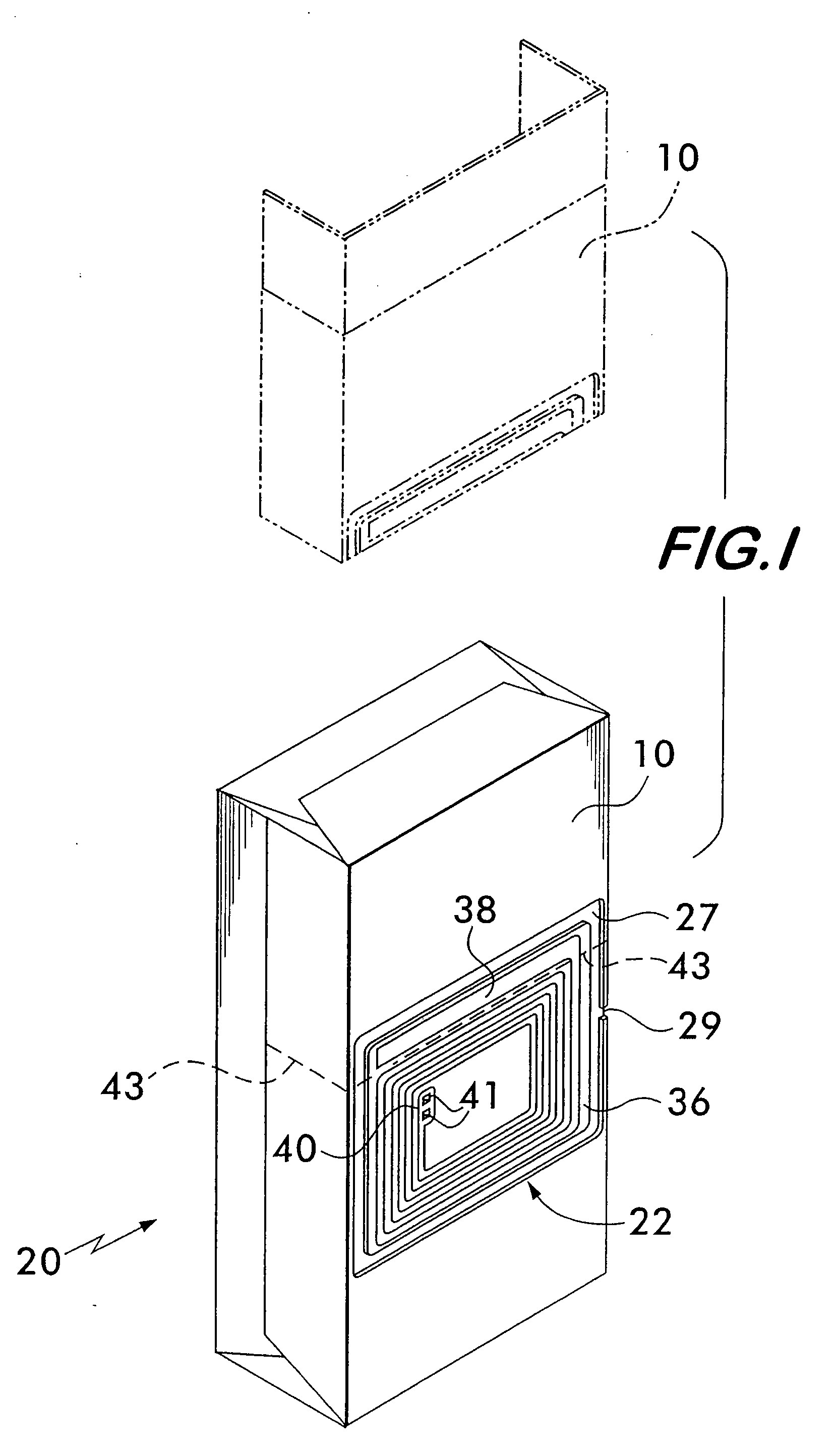
[0047]FIG. 15 shows the cutting edges 132A, 132B, 132C and 132D of the cutter 132 severing the metal layer 14 to form the antenna 124; in particular, these edges 132A-132D sever the non-adhesively secured portions (which corresponds to portion 135 as described previously) of the metal layer 14 but not the adhesively-secured portions of the metal layer 14 which forms the antenna 124. FIG. 16 is similar to the view of FIG. 15 but with the upper die 130 lifted away and with the severed portion 135 removed. Thus, the result of this process is a dipole antenna 124 (having elements 124A and 124B) which is isolated from the remaining portion ofthe metal layer 14, and wherein the metal layer 14 forms a nearly complete metal path around the central portion 127 except that it is interrupted by the channel 129, as can be seen most clearly in FIG. 13. It should noted that the presence of the channel 129 (e.g., approximately 0.10 inches), as discussed previously with respect to the first securit...

first embodiment

[0048]Once the antenna 124 is formed, the security tag 122 is completed by the application of a chip strap 125A (to form an RFID security tag) across the facing ends of dipole elements 124A and 124B of the antenna 124, as shown in FIGS. 11 and 14. As mentioned previously, the chip strap 125A comprises an RFID IC 125 and terminals 127A and 127B (FIG. 14) that are electrically coupled (e.g., crimp / adhesive mentioned previously with respect to the first embodiment) to respective dipole elements 124A and 124B to form the RFID security tag 122. Chip straps are known in the art, such as those shown in U.S. Pat. No. 6,940,408 (Ferguson, et al.); U.S. Pat. No. 6,665,193 (Chung, et al.); U.S. Pat. No. 6,181,287 (Beigel); and U.S. Pat. No. 6,100,804 (Brady, et al.), as well as in A.Ser. No. 60 / 730,053 and all of whose disclosures are incorporated by reference herein.

[0049]Once the security tag 122 is formed and the liner 20 and cigarette pack 16 assembled, to facilitate the deactivation of a ...


PUM


Abstract

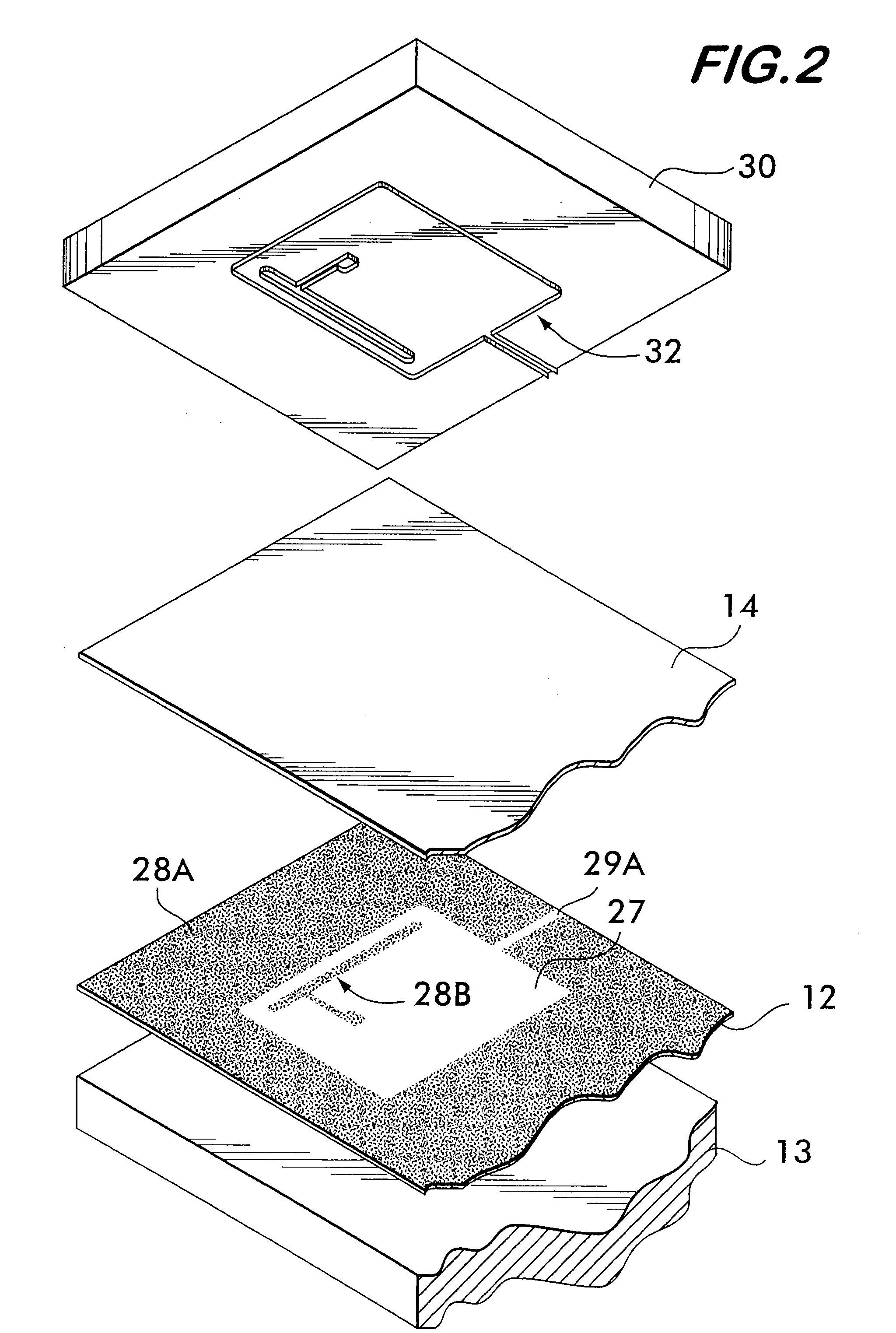
A cigarette pack having at least one security tag formed from the metal layer of the cigarette pack liner. One version of the security tag utilizes a preformed coil that is electrically coupled to a portion of the metal layer to form a capacitor and thereby complete a coil / capacitor security tag. Another version of the security tag is forms the entire antenna from the metal layer and a radio frequency identification (RFID) integrated circuit is then coupled to the antenna. In both versions, the surrounding metal layer is severed from the location of either security tag to the edge of the liner.

Description

CROSS-REFERENCE TO RELATED APPLICATIONS[0001]This utility application claims the benefit under 35 U.S.C. §119(e) of Provisional Application Ser. No. 60 / 752,987 filed on Dec. 22, 2005 entitled SECURITY TAG FOR CIGARETTE PACK and whose entire disclosure is incorporated by reference herein.BACKGROUND OF THE INVENTION[0002]1. Field of the Invention[0003]The current invention relates to security tags and more particulary, discloses integrating a security tag in the liner (e.g., aluminum) of a cigarette pack[0004]2. Description of Related Art[0005]Tracking or detecting the presence or removal of retail items from an inventory or retail establishment comes under the venue of electronic article surveillance (EAS), which also now includes radio frequency identification (RFID). EAS or RFID detection is typically achieved by applying an EAS or RFID security tag to the item or its packaging and when these security tags are exposed to a predetermined electromagnetic field (e.g., pedestals locate...

Claims


Application Information

Patent Timeline
Patent Type & Authority Applications(United States)
IPC IPC(8): G08B13/14
CPCB65D85/10B65D2203/10G06K19/07749G08B13/2414G08B13/242G08B13/2445
Inventor COTE, ANDRE
Owner CHECKPOINT SYST INC
Why Eureka
Try Eureka