

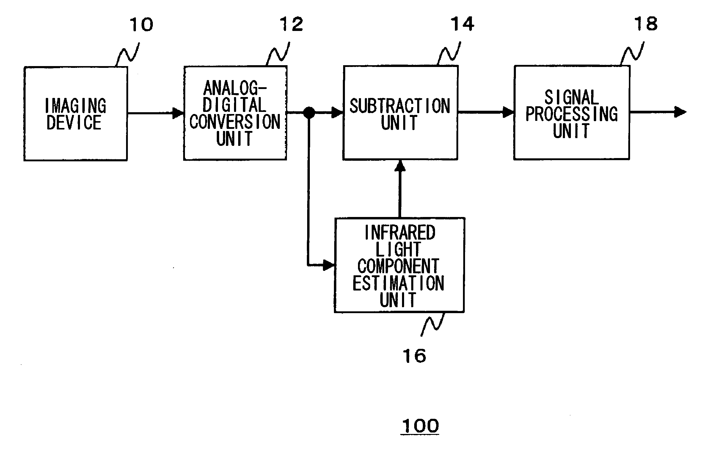
Imaging apparatus provided with imaging device having sensitivity in visible and infrared regions
a technology of visible and infrared regions and imaging devices, which is applied in the direction of picture signal generators, television system scanning details, television systems, etc., can solve the problems of uncomfortable feeling of the person taking the image, inability to obtain good color reproducibility, etc., and achieve good color reproducibility, good color reproducibility, and smooth switching
- Summary
- Abstract
- Description
- Claims
- Application Information
AI Technical Summary
Benefits of technology
Problems solved by technology
Method used
Image

Examples
first embodiment
[0063] In the first embodiment described above, an example has been shown in which, in the infrared light component estimation unit 16, the infrared light component IR outputted from the pixel provided with the infrared light filter is multiplied by the ratio of the spectral characteristics in the infrared region of the light received by each of the pixels provided with the respective visible light filters to the spectral characteristics of the light received by the pixel provided with the infrared light filter, and as such the infrared light component is corrected. However, for example, the infrared light component may be estimated as follows. The difference between the spectral characteristics in the infrared region of the light received by each of the pixels provided with the respective visible light filters and the spectral characteristics of the light received by the pixel provided with the infrared light filter is considered as an offset amount. Then, this offset amount is add...
second embodiment
[0087] For example, the infrared light component may be removed independently from a luminance component and a color component. FIG. 6 is a diagram illustrating the configuration of an imaging apparatus 2200 according to a first modified example of the present invention. This imaging apparatus 2200 includes a subtraction unit 2030 for luminance, an infrared light removal ratio determination unit 2032 for luminance, a subtraction unit 2034 for color, and an infrared light removal ratio determination unit 2036 for color, in place of the subtraction unit 2014 and the infrared light removal ratio determination unit 2016 of the imaging apparatus 2100 shown in FIG. 4. Hence, as for the luminance component, the infrared light component passing through each of the visible light filters can be effectively utilized by setting the coefficient K to be a small value, and as such the sensitivity can be increased. As for the color component, the infrared light component can be removed as much as p...
PUM
 Abstract
Description
Claims
Application Information