

Light deflector, optical scanner, and image forming apparatus
a light deflector and optical scanner technology, applied in optics, electrical devices, instruments, etc., can solve the problems of increasing the degree of misregistration of scan lines, the non-uniformity of scan line pitch, and the increase in the rotational speed of the mirror (scanning speed). achieve the effect of maintaining the accuracy of scan position disposition, good accuracy, and uniform scanning speed
- Summary
- Abstract
- Description
- Claims
- Application Information
AI Technical Summary
Benefits of technology
Problems solved by technology
Method used
Image

Examples
Embodiment Construction
[0042] A description is given, with reference to the accompanying drawings, of an embodiment of the present invention.
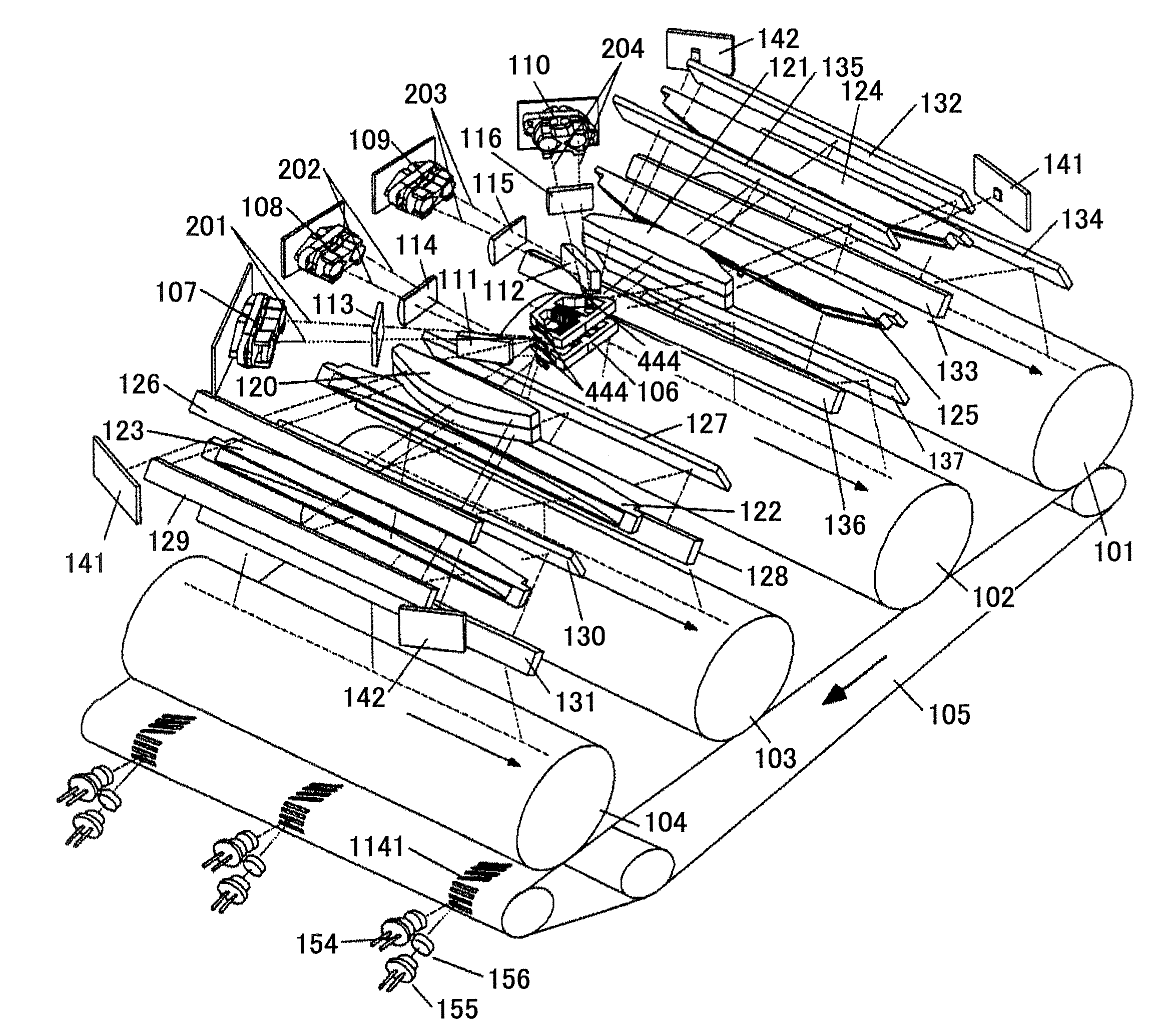
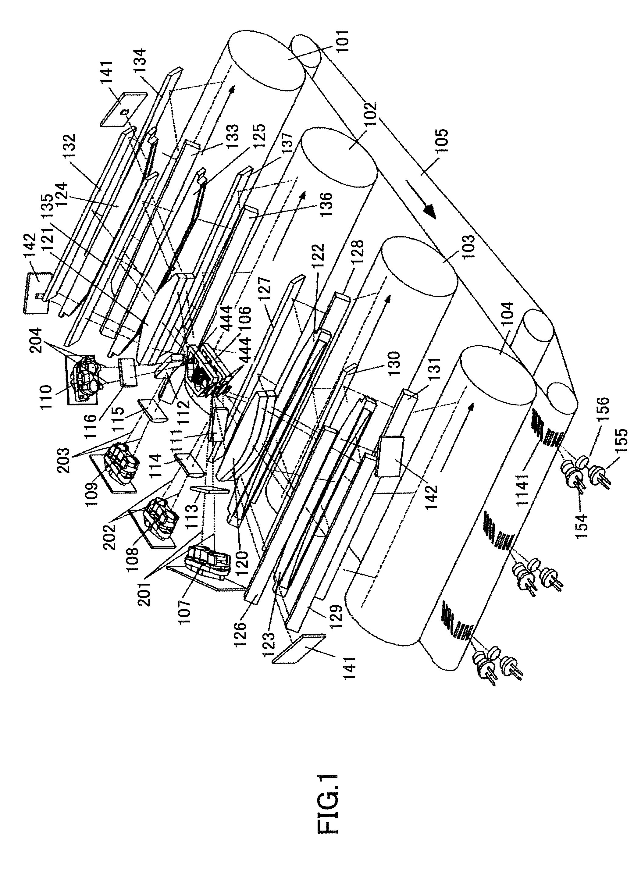
[0043]FIG. 1 is a perspective view of an optical scanner according to this embodiment. This optical scanner is provided in an electrophotographic image forming apparatus. The optical scanner performs scanning in four stations. The optical scanner employs an opposed scanning system in which the four stations are divided into two groups, two stations each, and light beams are made incident on a pair of moving mirrors from opposing sides thereof so as to be deflected in opposite directions and perform scanning.
[0044] Four photosensitive body drums 101, 102, 103, and 104 are disposed at equal intervals along a direction in which a transfer body such as paper moves (indicated by arrow in FIG. 1), so that toner images of different colors are successively transferred onto the transfer body so as to be superposed one over another, thereby forming a color image.
[0045] The ...
PUM
 Abstract
Description
Claims
Application Information