
Method for the mapping of packet flows to bearers in a communication system

Active Publication Date: 2007-06-28
NOKIA SOLUTIONS & NETWORKS OY
View PDF12 Cites 60 Cited by
  • Summary
  • Abstract
  • Description
  • Claims
  • Application Information

AI Technical Summary

Benefits of technology

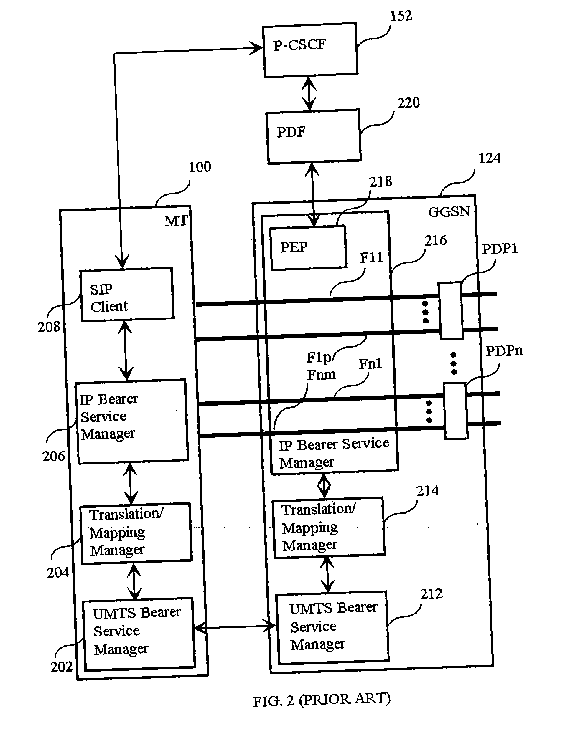
[0033] In one embodiment of the invention, the policy enforcement entity in the first network node obtains from said second network node a first data rate associated with a combination of said at least two packet flows. In other words, the first data rate is the sum of the data rates of the packet flows. The policy enforcement entity compares the sum of the data rates of said at least two bearers to said first data rate. Thereupon, in case the sum of the data rates of said at least two bearers exceeds said first data rate, the policy entity reduces the data rate of at least one bearer among said at least two bearers.

Problems solved by technology

In packet switched networks the transport technology inherently does not provide the users with guarantees involving the QoS available for a single user.
The problem in prior art solutions is that it is limited to using a binding mechanism based on an authorization token and flow identifiers.
Possible new binding mechanisms, which only support the providing of an IP Address or a user identity to a PDF, do not support the separation of the PDP contexts.
This means that the PDF authorizing the sessions of the mobile station cannot authorize the relevant QoS values for each PDP context.
This causes several practical problems.
For example, the mobile station may exceed the authorized bitrate, which results in the waste of network resources and bandwidth.
Further, downlink packets have to be sent through all SBLP controlled PDP contexts, because the network does not know which context the mobile station is using for given media flows, which results into the waste of resources and a risk of jamming the traffic channel.
Further, the mobile station may exceed the QoS class in some PDP contexts, which also amounts to waste of network resources and bandwidth.

Method used


Image

  • Method for the mapping of packet flows to bearers in a communication system
  • Method for the mapping of packet flows to bearers in a communication system
  • Method for the mapping of packet flows to bearers in a communication system

Examples


Embodiment Construction

[0052] Reference will now be made in detail to the embodiments of the present invention, examples of which are illustrated in the accompanying drawings.

[0053]FIG. 4A is a block diagram illustrating Quality of Service (QoS) authorization signaling at Packet Data Protocol (PDP) context establishment phase in one embodiment of the invention. In FIG. 4A there is a Gateway GPRS Support Node (GGSN) 450 and a Policy Decision Function (PDF) 460. A mobile station (not shown) communicates with GGSN 450. Within GGSN 450 there is a Policy Enforcement Entity 452, which is comprised in IP Bearer Service Manager 452. The starting point in FIG. 4A is that the mobile station (not shown) has exchanged SIP signaling information with a remote terminal. The signaling information has been intercepted in PDF 460, which has determined from the session description protocol definitions the IP flows and the bi-directional combinations of these IP flows that are associated with the session. There are three bi...


PUM


Abstract

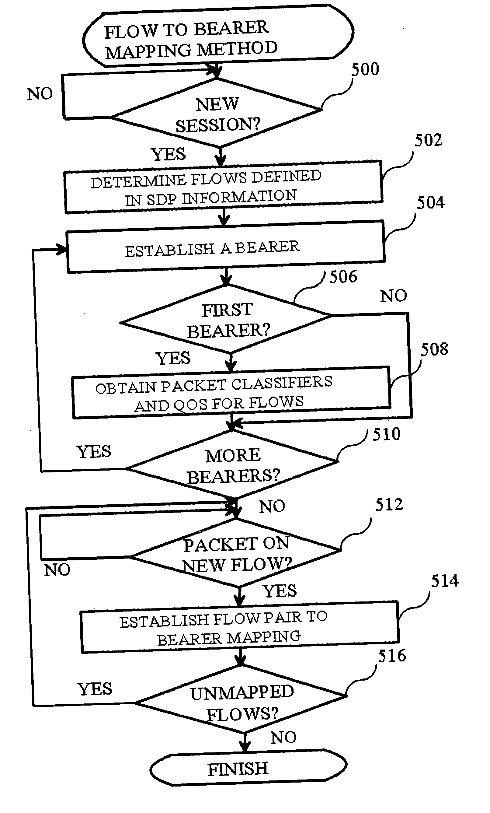
The invention relates to a method for the mapping of packet flows onto bearers in a communication system. The establishment of a session between a terminal and a remote terminal is initiated. Information on the session and packet flows associated with it is received to a second network node. A first network node obtains from the second network node one or two packet classifiers for each of the packet flows. At least a first bearer belonging to the bearers is established between the terminal and the first network node. A packet associated with the first bearer is received in the first network node. The packet is matched with the one or two packet classifiers associated with each of the packet flows to determine a first packet flow among the packet flows. A mapping is established between the first packet flow and the first bearer in the first network node.

Description

BACKGROUND OF THE INVENTION [0001] 1. Field of the Invention [0002] The invention relates to Quality of Service (QoS) in packet switched communication systems. Admission control is applied for packet flows, which are transmitted using bearers. Particularly, the invention relates to a method for the mapping of packet flows to bearers in a communication system. [0003] 2. Description of the Related Art [0004] The transport of voice and multimedia over packet switched networks has in the recent years emerged as a viable alternative for traditional circuit switched networks. In circuit switched networks resource allocation is based on the allocation of entire physical circuits or repeating timeslots within physical circuits for users. From an abstract point of view the transport technology relieves the network of the complexity involving admission control and Quality of Service (QoS) allocation. In packet switched networks the transport technology inherently does not provide the users wi...

Claims


Application Information

Patent Timeline
IPC IPC(8): H04L12/26H04L12/54H04W28/16
CPCH04L12/5695H04L47/10H04L47/14H04L47/15H04L47/2441H04L47/2491H04W28/16H04L47/786H04L47/801H04L47/805H04L47/824H04L47/829H04L47/25H04L47/70H04W28/0263H04W8/04
Inventor RASANEN, JUHA
Owner NOKIA SOLUTIONS & NETWORKS OY
Learn More