Location determination techniques

a technology of location determination and location, applied in the field of location determination techniques, can solve the problems of high computational load, inability to model the movement of target objects using conventional techniques, and inability to achieve the effect of ensuring robustness and being easy to understand

Active Publication Date: 2007-06-28
OY EKAHAU +2
View PDF6 Cites 202 Cited by
  • Summary
  • Abstract
  • Description
  • Claims
  • Application Information

AI Technical Summary

Benefits of technology

[0021] An advantage of the invention is a certain robustness, which stems at least partially from the fact that the plurality of particles cope with unexpected target object movements better than most prior art techniques which attempt to fit a single motion model to a target object.
[0022] The invention is based on the idea that prior art techniques for estimating a target object's location are deterministic, and such deterministic approaches encounter severe problems in unforeseen or unlikely situations. The inventive technique is based on the use of a plurality of particles which collectively estimate the target object's properties, such as location. When the target object makes an improbable move or turn, the deterministic techniques tend to become confused. The particles according to the present invention, however, develop in a manner which is largely equivalent to natural evolution. The particles which best model the target object's properties tend to have a higher likelihood of having descendent particles in the next cycle, whereby poorly-fitting particles tend to die out. Even in highly unlikely situations, when most particles are wiped out, a small number of particles survive to following cycles.
[0023] In a typical implementation of the invention, the set of properties of the target object comprises the target object's location, or a location-related property of the target object. Examples of location-related properties include time derivatives of location, such as velocity and acceleration. In a typical implementation, the target object's location or location-related property is determined at least temporarily. A temporary determination of target object's location means, for example, that the target object's location is determined but only used as a temporary quantity for determining one or more further location-dependent quantities, after which the location may be discarded or concealed from external entities. In order to make the following description of the invention easier to understand, the description is based on the assumption that the invention will be used to determine at least the location of the target object. However, it is to be noted that useful location-dependent services may be provided without revealing or even internally determining the target object's location in any coordinate system. In other words, the location does not necessarily involve any metrics, and any or some of the locations may be expressed in abstract terms, such as an arbitrary node identifier in a topology model, or by means of some naming convention, such as “room 123”.
[0024] In the above definition of the invention, the sensing device means a device which is able to make observations of one or more location-dependent physical quantities in the environment. A non-exhaustive list of applicable physical quantities includes:
[0025] radiometric signal quality values, such as signal strength, signal-to-noise ratio, bit error rate / ratio, timing advance, or the like; such signal quality values, if used, are preferably determined separately for each of several frequency bands, channels, cells, base stations or the like;
[0026] atmospheric physical quantities, such as air pressure, temperature, humidity, or the like;

Problems solved by technology

Conventional techniques have problems in modelling the target object's movement.
Increasing the number of possible states increases the number of state transitions rapidly, which consumes memory and causes a high computational load.

Method used


Image

  • Location determination techniques
  • Location determination techniques
  • Location determination techniques

Examples


Embodiment Construction

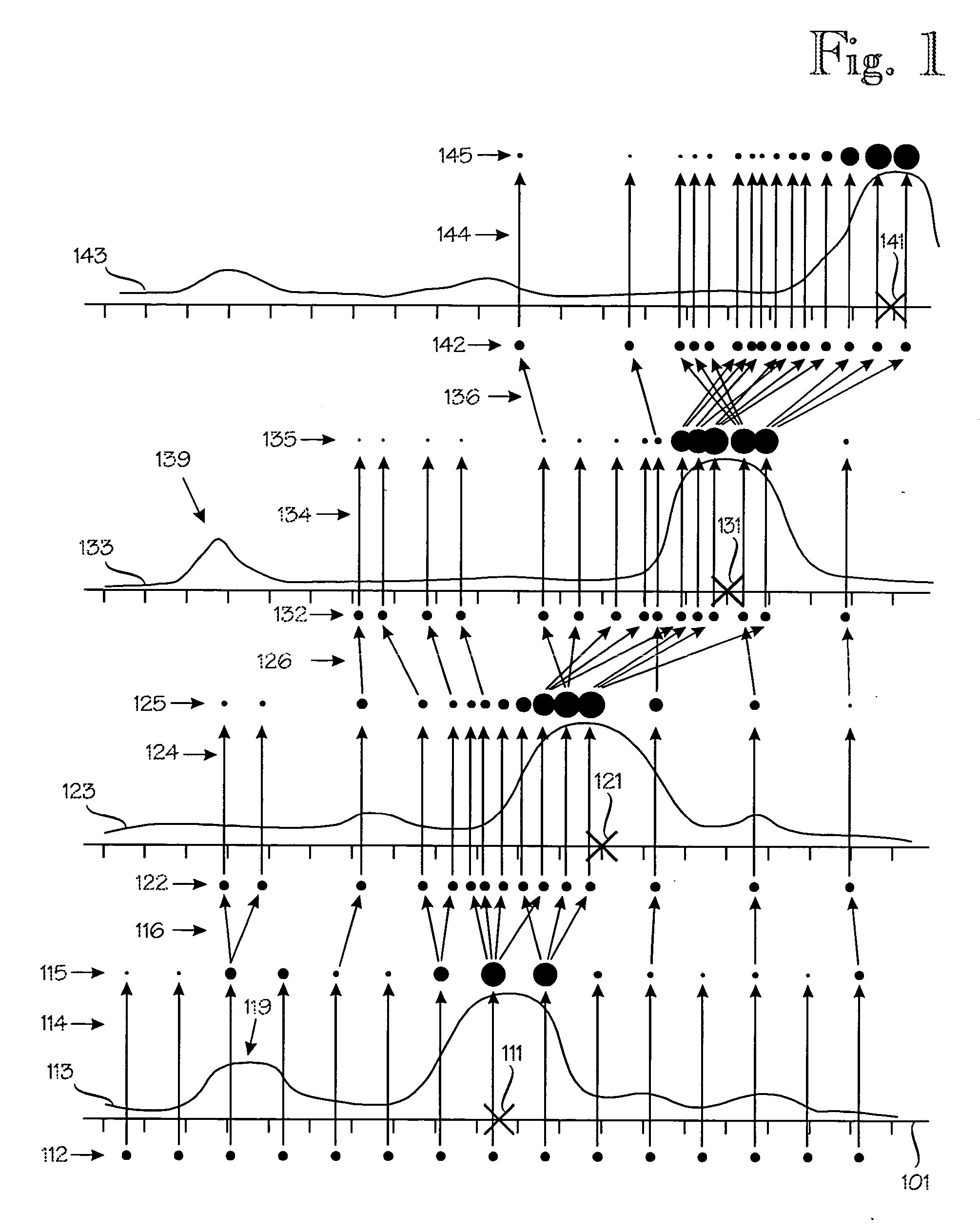
[0092]FIG. 1 illustrates an operating principle of the invention. The description of Figure is based on the assumption that the target object's property set is or comprises the target object's location. Reference numeral 101 denotes a path of the target object. The path 101 is provided with evenly-spaced tick marks. In the description of FIG. 1, the path is assumed to resemble a track along which the target object can only move forwards or backwards (to the left or right in FIG. 1).

[0093]FIG. 1 illustrates a process of performing four consecutive location estimation cycles for the target object. Each estimate is made at a specific instance of time. Time advances from bottom to top. Reference numerals 111-116 relate to the first location estimate, reference numerals 121-126 to the second estimate, and so on. Reference numeral 111 denotes the target object's location along the path 101. Naturally, the target object's location 111 is not known to the location estimation routine and is...


PUM


Abstract

A method for estimating a target object properties, including location, in an environment. A topology model indicates permissible locations and transitions and a data model models a location-dependent physical quantity which is observed by the target object's sensing device. Motion models model specific target object types, obeying the permissible locations and transitions. The target object is assigned a set of particles, each having a set of attributes, including location in relation to the topology model. The attributes estimate the target object properties The particles' update cycles include: determining a degree of belief for each particle to estimate the target object properties; determining a weight for each particle based on at least the determined degree of belief and generating new particles for update cycle n+1 in an evolutionary process.

Description

BACKGROUND OF THE INVENTION [0001] The invention relates to methods, apparatus and software products for determining a set of properties of a target object in an environment. Illustrative examples of the target object include a person, animal, vehicle, instrument, shopping cart or project folder. An illustrative example of the target device property set includes location. An illustrative but non-restrictive application of the invention involves locating a wireless mobile terminal in a wireless communication environment, such as in a wireless local-area network (WLAN) or cellular network. [0002] U.S. Pat. No. 6,393,294 to Luis Perez-Breva et al. discloses a representative prior art technique for locating a mobile unit in wireless communication system. The location of a remote mobile unit is determined by comparing a snapshot of a predefined portion of the radio-frequency spectrum taken by the mobile unit to a reference database containing multiple snapshots taken at various locations...

Claims


Application Information

Patent Timeline
Patent Type & Authority Applications(United States)
IPC IPC(8): H04Q7/20H04W64/00
CPCG01S5/0252H04W64/00G01S5/02524
Inventor MISIKANGAS, PAULI
Owner OY EKAHAU
Why Eureka
Try Eureka