Hinged roof vent for attic

a roof vent and attic technology, applied in ventilation systems, lighting and heating apparatus, heating types, etc., can solve the problems of increasing the temperature within the structure, leaking roof vents, and increasing installation costs

Inactive Publication Date: 2007-07-05
OWENS CORNING INTELLECTUAL CAPITAL LLC
View PDF33 Cites 19 Cited by
  • Summary
  • Abstract
  • Description
  • Claims
  • Application Information

AI Technical Summary

Benefits of technology

[0007] A hinged roof vent panel for use at the eaves of a building structure is disclosed. The hinged panel includes flanges that have a hinge, walls raised from the lateral flanges and insulation blocking walls raised from above the flanges by the walls to form ventilation troughs. Each insulation blocking wall includes a hinge and a cut marking line and the cut marking line separates the insulation blocking wall into an insulation damn and a vent portion. In one embodiment of the invention, the hinge is positioned on the insulation damn portion. In another embodiment, gussets and / or saddles may be formed along the lateral walls. In yet another embodiment, the roof vent includes a number insulation blocking walls with a base positioned between the insulation blocking walls. The base preferably includes a perforation that allows the panel to be divided without the use of a cutting tool. In yet another embodiment, a trapezoidal ridge extends substantially the length of the panel. The trapezoidal ridge includes a land that is level with the insulation blocking wall. Preferably, the base of the trapezoidal ridge is sized to allow the use of an air-nailer or stapler to secure the panel to the roof deck. Preferably, the hinged roof vent panel is formed of an extruded foam polystyrene sheet.

Problems solved by technology

Due to the position of the soffit vents, heat loss at the eaves may occur and with freezing and thawing temperatures, ice dams may form at the eaves, thereby causing roof leaks usually in the coldest of weather.
In the summer, improper ventilation of the attic causes heat to buildup within the attic, which will increase the temperature within the structure.
The number of steps required to install the hinged roof vent increases the cost of installation.
In addition, the complexity of the vent increases production costs such as the cost of manufacturing the mold for forming the vent.

Method used


Image

  • Hinged roof vent for attic
  • Hinged roof vent for attic
  • Hinged roof vent for attic

Examples


Embodiment Construction

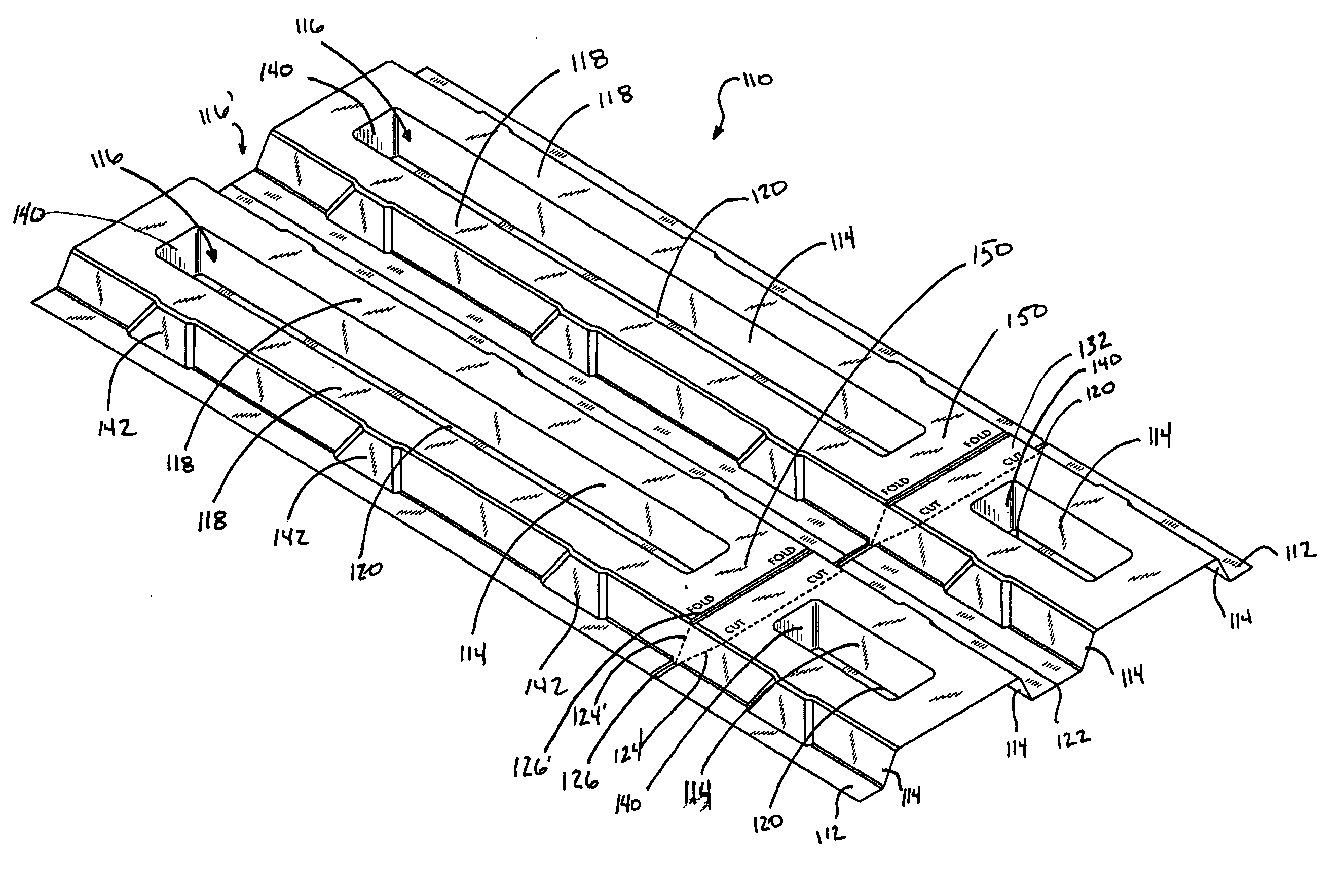
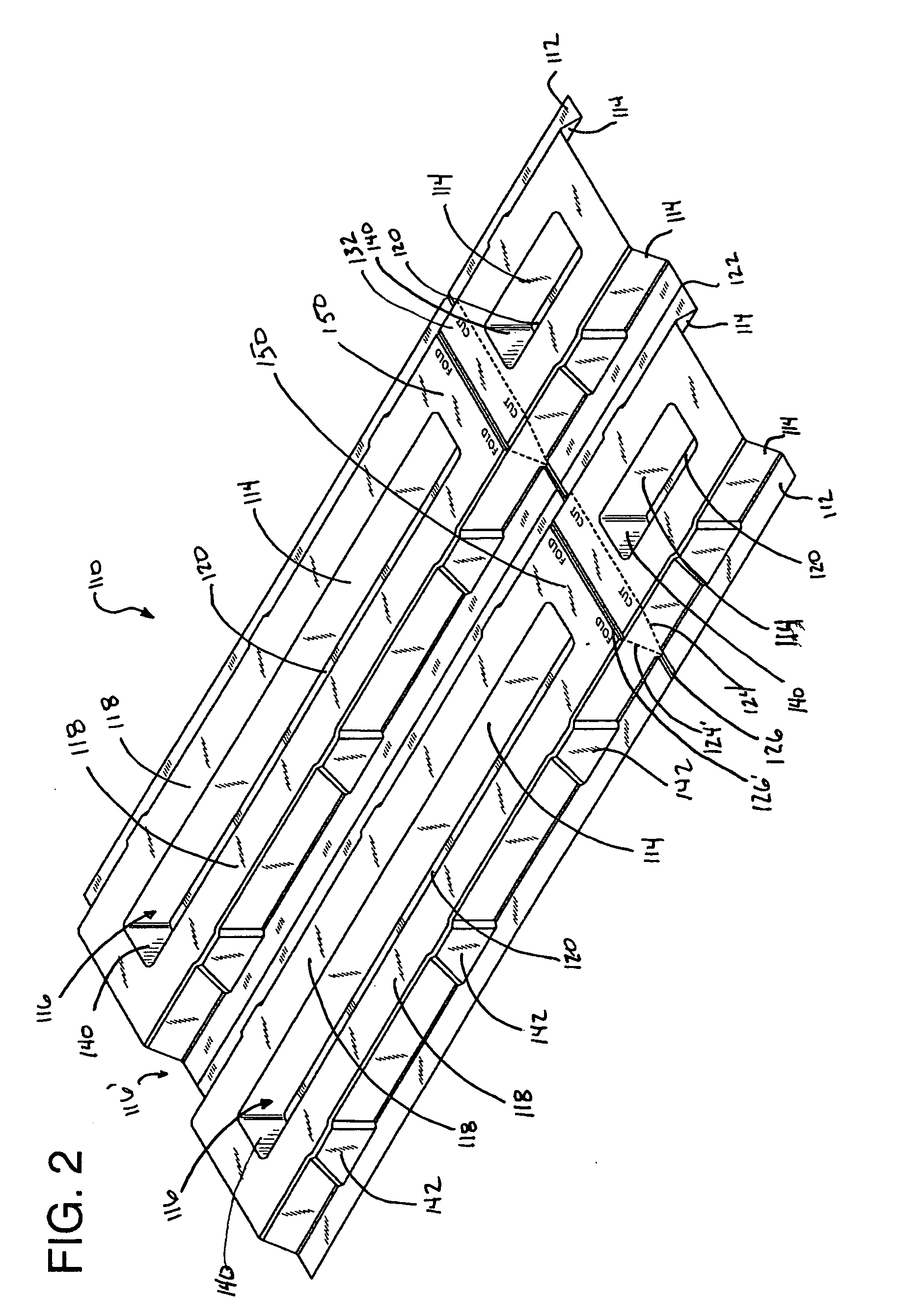
[0014] A hinged roof vent panel is provided which includes a combination of hinged ridges that allow the panel to be cut and folded to form an insulation block. The insulation block inhibits the flow of loosefill insulation which may block soffit vents and which provides suitable ventilation to inhibit condensation during cold periods and to allow acceptable airflow during warm periods. The vent panel may be thermoformed from a thin sheet of extruded polystyrene foam into the shape described and claimed herein. The panel is relatively planar and stackable so that a large number of panels may be packaged together for shipping.

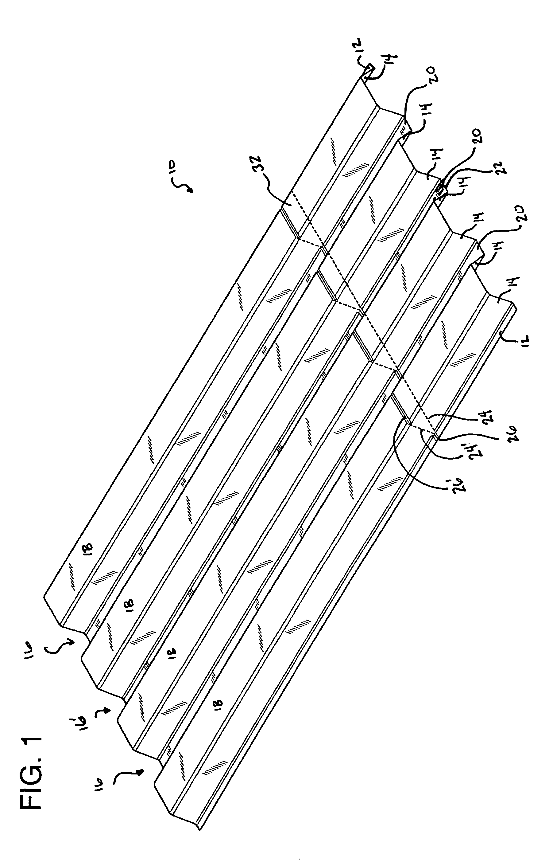
[0015] As shown in FIG. 1, a hinged roof vent panel 10 in accordance with one embodiment of the present invention is formed with edge flanges 12 and sloping lateral walls 14 which extend upwardly to offset insulation blocking segments 18 that are positioned parallel to but raised from flanges 12 and bases 20 of trapezoidal ridges 16 and 16′. Next to the offset ...


PUM


Abstract

A hinged roof vent panel is provided which includes a combination of hinged ridges that allow the panel to be cut and folded to form an insulation block which inhibits the flow of loosefill insulation which may block soffit vents and which provides suitable ventilation to inhibit condensation during cold periods and to allow acceptable airflow during warm periods. The vent panel is typically thermoformed from a thin sheet of extruded polystyrene foam into the shape described and claimed. The panel is relatively planar and stackable so that a large number of panels may be packaged together for shipping.

Description

TECHNICAL FIELD AND INDUSTRIAL APPLICABILITY OF THE INVENTION [0001] This invention relates generally to a panel for use as a roof vent, and more particularly, to a hinged vent panel for use on a sloping roof to allow for attic ventilation and to inhibit the flow of insulation out of an attic area into the soffit of a structure to block a soffit attic vent. BACKGROUND OF THE INVENTION [0002] Homes and commercial buildings with sloped or pitched roofs typically include an open, unheated attic. The area of the attic is typically insulated by a layer of fibrous insulation, for example, loosefill fiberglass, batts or rolls of fiberglass insulation, or other insulation materials such as cellulose, mineral wool. Building codes often require that an unheated attic be vented to release heat and moisture that may otherwise build up. Often the vents are positioned in the soffit at the eaves of the house to allow airflow from the soffit vents to the peak vents. Due to the position of the soffi...

Claims


Application Information

Patent Timeline
Patent Type & Authority Applications(United States)
IPC IPC(8): E04B7/00
CPCF24F7/02E04D13/178
Inventor MUMAW, JOHN R.BERDAN, CLARKE II
Owner OWENS CORNING INTELLECTUAL CAPITAL LLC
Why Eureka
Try Eureka