Bar material supply device of numerically controlled automatic lathe

a technology of numerical control and automatic lathe, which is applied in the direction of automatic conveying/guiding stock, turning machine accessories, manufacturing tools, etc., can solve the problems of complex structure and unsuitable feeding, and achieve the effects of shortening material feeding time, shortening machining time, and miniaturizing the configuration of the bar material supply devi

Inactive Publication Date: 2007-07-05
CITIZEN WATCH CO LTD
View PDF12 Cites 13 Cited by
  • Summary
  • Abstract
  • Description
  • Claims
  • Application Information

AI Technical Summary

Benefits of technology

[0036] With this configuration, the bar material can be sent from the stocker on the spindle axis in the middle of retreatment of the push rod, and a bar material to be machined next can wait in a position near the spindle axis. Hence, bar material feeding time can be shortened to shorten machining time.
[0037] According to the present invention thus configured, the configuration of the bar material supply device can be greatly simplified, miniaturized, and reduced in weight. Hence, the bar material supply device can be integrally attached to the headstock, whereby the numerically controlled automatic lathe equipped with the bar material supply device can be made compact and reduced in cost. Furthermore, the bar material supply device of the present invention is suited to machining of a short bar material such as an end material or a bar material having a polygonal sectional shape.

Problems solved by technology

However, the technologies of the foregoing Patent References 2, 3 are both for directly feeding the bar material to be machined by the carrier rollers, and not suited for feeding a short material which has become an end material in cutting and machining, or a bar material whose sectional shape is other than a circle, e.g., a bar material having a polygonal sectional shape such as a triangle, a square, or a hexagon, to the spindle.
However, a mechanism for distributing driving forces in good balance to the carrier rollers 8a, 8b, and a mechanism for retreating both of the carrier rollers 8a, 8b from the bar material when the machining of the bar material is started, become necessary, resulting in a drawback of a complex structure.

Method used


Image

  • Bar material supply device of numerically controlled automatic lathe
  • Bar material supply device of numerically controlled automatic lathe
  • Bar material supply device of numerically controlled automatic lathe

Examples


first embodiment

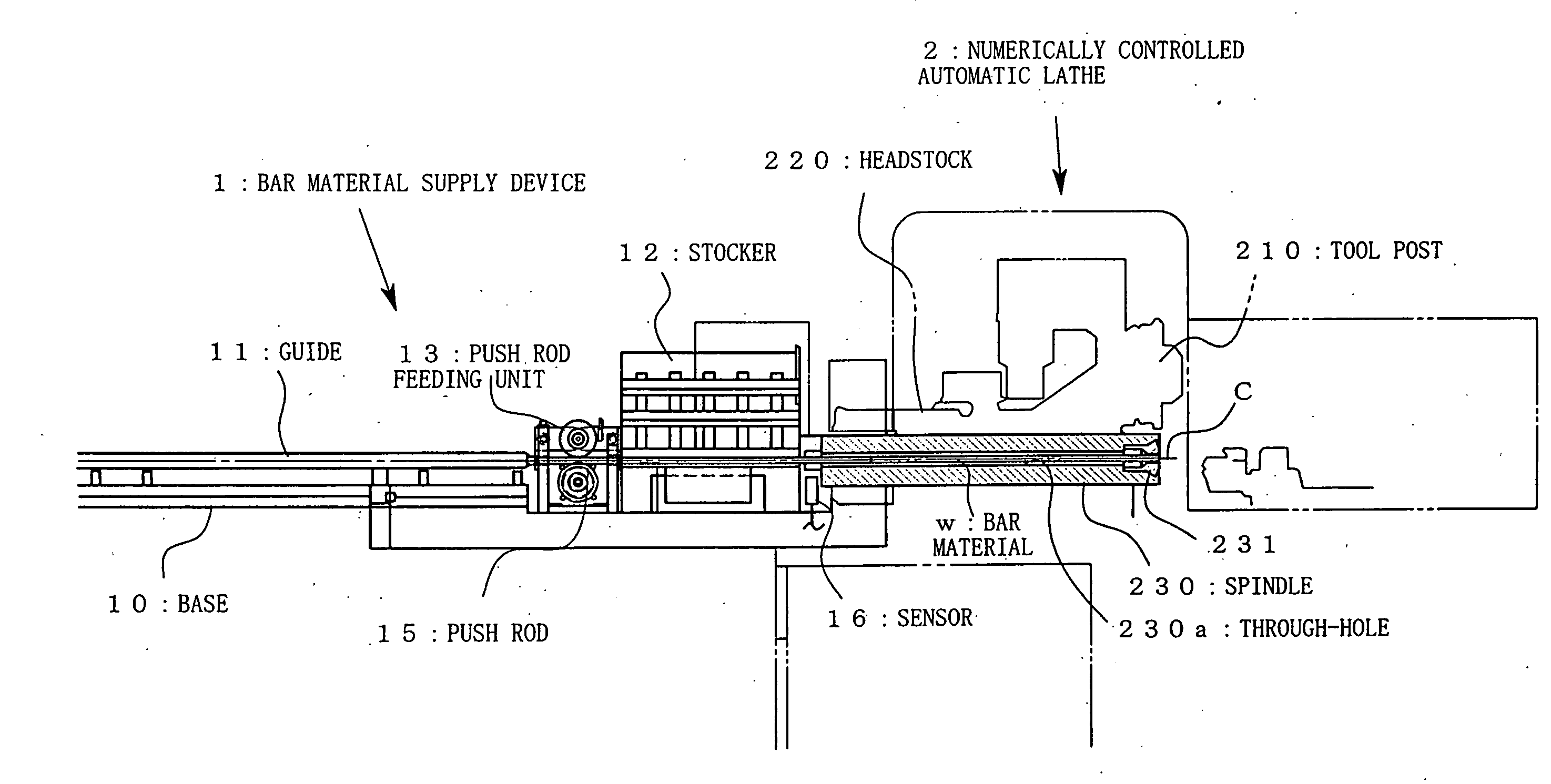
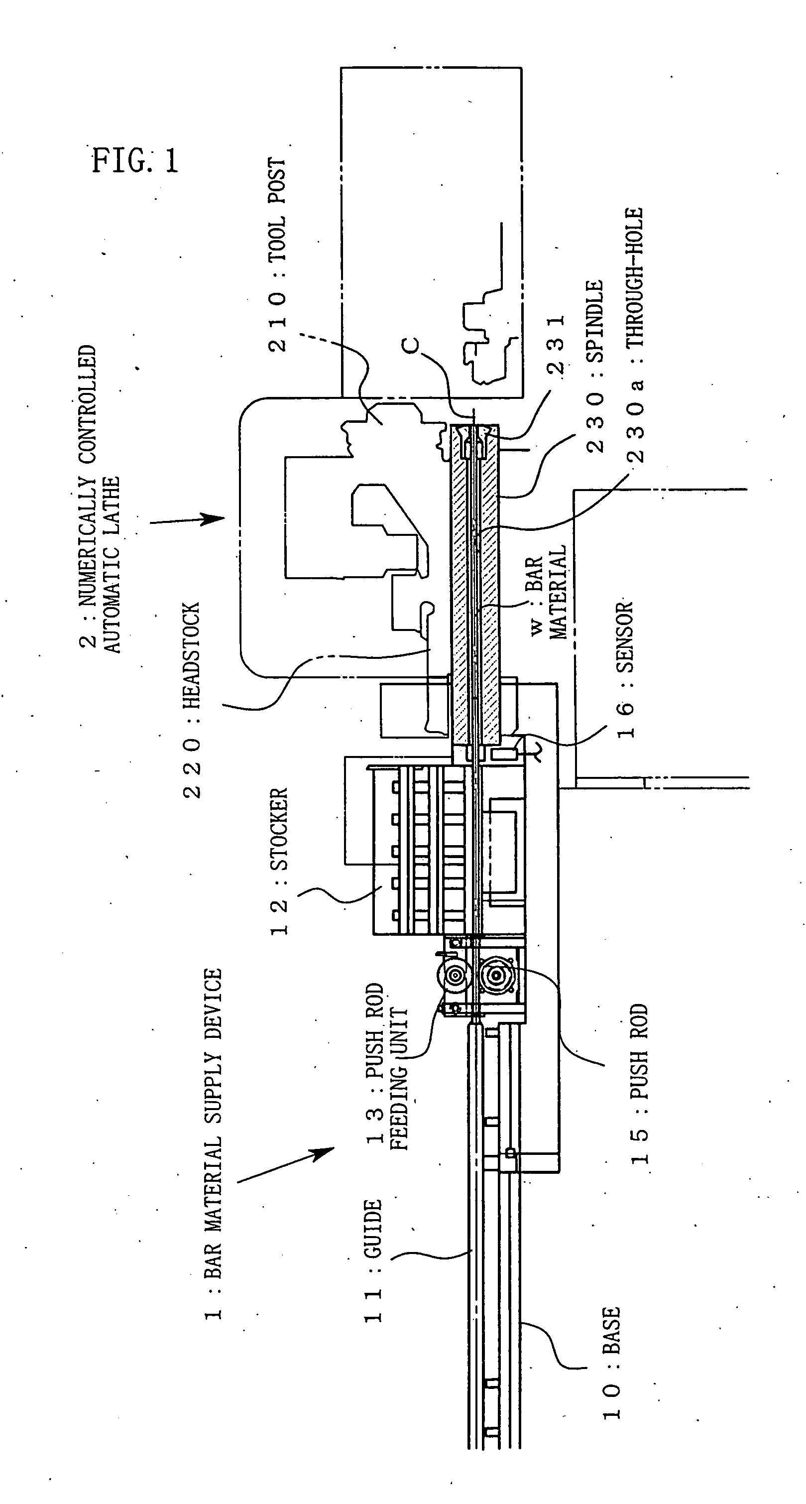
[0074]FIG. 1 is an explanatory front view of an entire configuration of a bar material supply device according to the present invention.

[0075] In the description below, “Front” means a front end side of a spindle having a chuck disposed to grip a bar material, i.e., a right side of FIG. 1, and “Rear” means a left side of FIG. 1. In the description below, a numerically controlled automatic lathe is presumed to be an automatic lathe of a spindle moving type which has a headstock freely movable in the same direction (Z axis direction) of an axis C of the spindle.

[0076] [Outline of Numerically Controlled Automatic Lathe]

[0077] A spindle 230 having a through-hole 230a in the same direction as the spindle axis C is supported on a headstock 220 of a numerically controlled automatic lathe 2 to freely rotate. A bar material 1 is inserted into the through-hole 230a from a rear end of the spindle 230, and guided through the through-hole 230a to a front end of the spindle 230. A chuck 231 is d...

second embodiment

[0123] Hereinafter, a second embodiment in the case of the spindle fixed type will be described with reference to a flowchart of FIG. 9, and operation views of FIGS. 10(a) to 12(b).

[0124] Components of a bar material supply device of the embodiment are similar to those of the first embodiment except for the fact that a headstock 220 is a fixed type and a base 10 is integrally mounted to the headstock 220. Thus, similar reference numerals will be used for similar members and portions, and detailed description of the configuration of the bar material supply device 1 will be omitted.

[0125] After turning-ON of power for the bar material supply device 1 and a numerically controlled automatic lathe, before supplying of a bar material w by the bar material supply device 1, determination is made as to whether a push rod 15 has retreated to a position (last retreating position) to abut on a stopper 12 or not (step S201, FIG. 10(a)). The retreatment of the push rod 15 to the position to abut...


PUM

PropertyMeasurementUnit
forceaaaaaaaaaa
movementaaaaaaaaaa
shapeaaaaaaaaaa

Abstract

There is provided a bar material supply device of a simple configuration suited to machining of a bar material without increasing machining cost even when a short bar material such as an end material is machined. The bar material supply device includes a stocker 12 for supplying a bar material w on an axis C of a spindle 230, a base 10 attached to a head stock 220, a push rod 15 disposed in the base 10 to move back and forth on the axis C and to push the bar material w fed from the stocker 12, a push rod guide 11 disposed in the base 10 to guide the back-and-forth movement of the push rod 15, a plurality of rollers arranged on both sides of the axis C of the base 10 to hold the push rod 15 on the axis C therebetween, one of the plurality of rollers being constituted as a driving roller 135 which is rotated by a driving body disposed in the base, and at least one of the other rollers excluding the driving roller 135 being constituted as a driven roller 132 which is rotated without any slippage with the push rod 15, and rotation detection means 133 for detecting the rotation of the driven roller 132.

Description

TECHNICAL FIELD [0001] The present invention relates to a bar material supply device for machining a bar material while sending it through a through-hole of a spindle of a numerically controlled automatic lathe. BACKGROUND ART [0002] In a numerically controlled machine tool such as a numerically controlled automatic lathe, a long bar material may be used as a material when a relatively small product is machined. As a machining method of this type based on the numerically controlled automatic lathe, there has conventionally been known an art of feeding a bar material to a portion to be machined from a rear side of the numerically controlled automatic lathe by a bar material supply device, and rotating the bar material together with a spindle to cut and machine a front end of the bar material into a predetermined shape (e.g., see Patent Reference 1). [0003] Patent Reference 1: JP A 2001-246502 (refer to FIG. 1 of the drawings, and a paragraph [0008] of the description). [0004]FIG. 14 ...

Claims


Application Information

Patent Timeline
Patent Type & Authority Applications(United States)
IPC IPC(8): B23B13/00B23B13/02B23B13/12
CPCB23B13/021B23B13/128Y10T82/2521Y10T82/2518Y10T82/2514B23B13/02B23B13/00
Inventor NAKAYA, TAKAICHIKAWAKUBO, TAKASHIIIDA, TADAHIRONONAKA, YOUHEI
Owner CITIZEN WATCH CO LTD
Why Eureka
Try Eureka