Onboard modular optronic system

Inactive Publication Date: 2007-07-05
THALES SA
View PDF14 Cites 21 Cited by
  • Summary
  • Abstract
  • Description
  • Claims
  • Application Information

AI Technical Summary

Benefits of technology

[0006] The present invention provides a way of overcoming the abovementioned drawbacks by proposing a new, modular onboard optronics system design, which can be adapted to any type of carrier and offers wide-ranging upgradeability potential without a new system having to be redeveloped.
[0008] The structure equipped with a module forming a section and intended to receive the optomechanical assembly also offers enhancements in terms of mechanical stabilization performance and reduced aero-optical effects.

Problems solved by technology

This variant has the particular drawback of limiting the number of sensors that can be installed and making it very difficult, even impossible, to upgrade the sensors, and in particular the laser, because a change of any one of these elements placed in the gimbal joint will entail redimensioning all the gimbal joint.
This makes it possible to upgrade the sensors and / or the laser, but increases the length of the front section and its weight, which adversely affects the mechanical stability of the assembly.
However, this extremely compact architecture, like the one described previously, is fixed, and any change of specifications to a sensor or to the laser will entail a complete redimensioning of the system.
Thus, the equipment known from the prior art must be developed specifically for a given type of carrier, such as a combat aircraft, a helicopter or a drone; there is only very little synergy between them, so their development costs are high, which means that unit costs are high because of the small quantities produced.
The costs of ownership, maintenance, stocks of spares and training are also consequently very high.
Furthermore, they are difficult to upgrade because of their fixed architecture.

Method used


Image

  • Onboard modular optronic system
  • Onboard modular optronic system
  • Onboard modular optronic system

Examples


Embodiment Construction

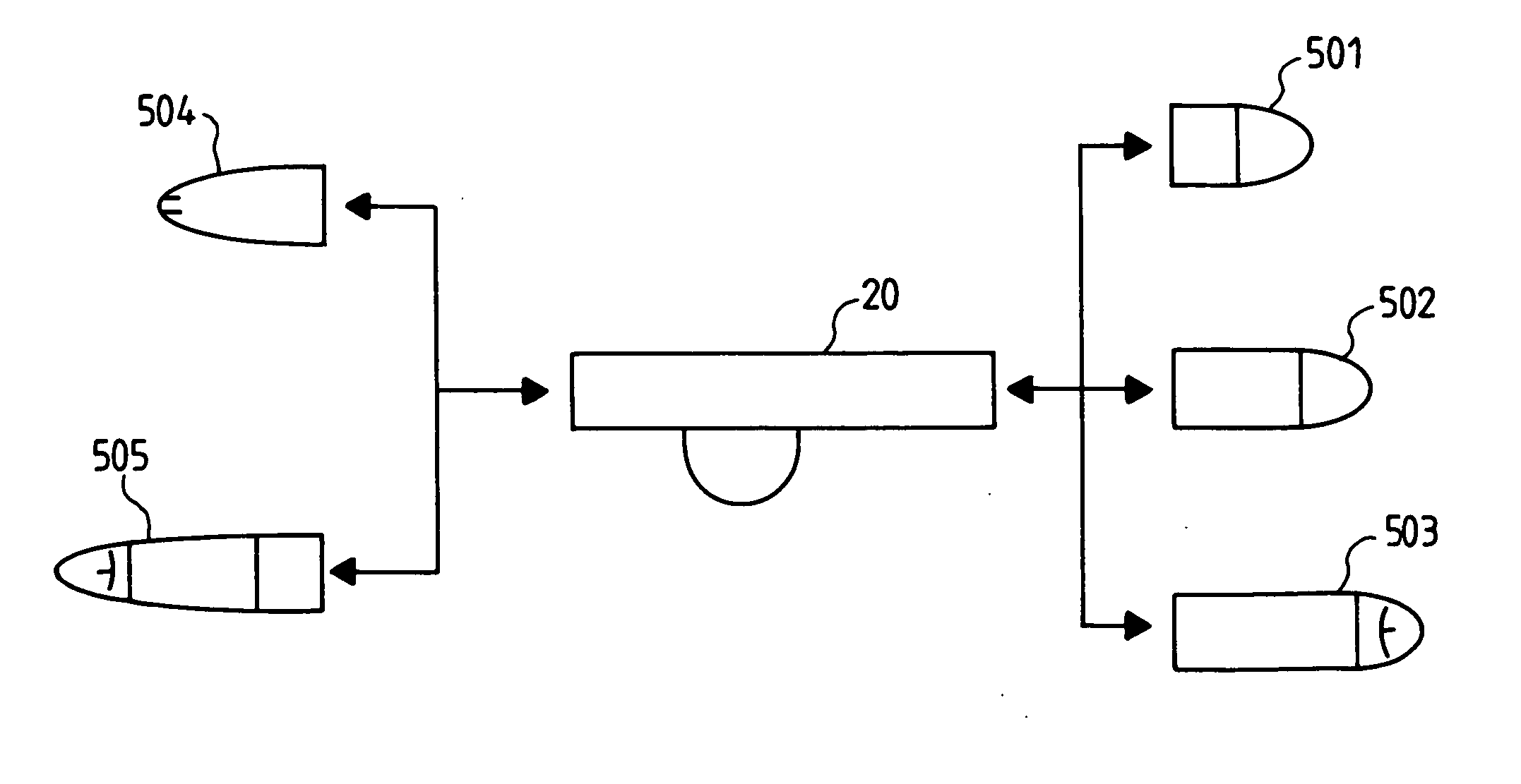
[0017] The onboard optronics system according to the invention comprises at least one optronics sensor, for example a camera, defining a target line which needs to be able to be addressed in a given space. It can also comprise a laser, for example for designating a target. It is equipped with a mechanism for stabilizing and orienting the target line or lines defined by the or each sensor, and by the laser where appropriate. According to the invention, the system is modular, comprising in particular a mechanical structure designed to be the interface with the carrier, said mechanical structure comprising a central module forming a section with three interfaces, namely said interface with the carrier and two lateral interfaces that can receive other modules. According to the invention, the target line orientation and stabilization mechanism is directly incorporated in the central module forming a section. The advantages of such a structure are manifold. Since the opto-mechanical compo...


PUM


Abstract

The present invention relates to a modular optronics system onboard a carrier, such as a combat aircraft, a helicopter or a drone. The system as claimed in the invention comprises at least one optronics element having a target line that can be addressed in a given space, and comprising a mechanical structure designed to be the interface with the carrier and a target line orientation and stabilization mechanism. According to the invention, the mechanical structure comprises a module forming a section with three interfaces, including said interface with the carrier and two lateral interfaces that can receive a lateral module. The optronics elements and the target line orientation and stabilization mechanism are directly incorporated in the module forming a section.

Description

CROSS-REFERENCE TO RELATED APPLICATIONS [0001] The present Application is based on International Application No. PCT / EP2004 / 053379, filed on Dec. 9, 2004, which in turn corresponds to FR 03 / 14600 filed on Dec. 12, 2003, and priority is hereby claimed under 35 USC §119 based on these applications. Each of these applications are hereby incorporated by reference in their entirety into the present application. TECHNICAL FIELD [0002] The present invention relates to a modular optronics system onboard a carrier, such as a combat aircraft, a helicopter or a drone. BACKGROUND OF THE INVENTION [0003] Most airborne optronics systems intended for observation, reconnaissance and laser designation take the form of a pod with a pointed mobile turret at the front, or of a sphere incorporating all the sensors. [0004]FIGS. 1A and 1B thus respectively represent a pod type system and a sphere type system, according to the prior art. In FIG. 1, the pod 10 comprises a front section 101 equipped with one...

Claims


Application Information

Patent Timeline
IPC IPC(8): B64C39/02B64D47/00B64D7/00B64D47/08G02B27/64G03B15/00
CPCB64D7/00G02B27/648B64D47/08B64U20/87
Inventor MOREAU, DOMINIQUE
Owner THALES SA
Why Eureka
Try Eureka