Ultra-miniature fiber-optic pressure sensor system and method of fabrication

Active Publication Date: 2012-08-23
UNIV OF MARYLAND
View PDF0 Cites 27 Cited by
  • Summary
  • Abstract
  • Description
  • Claims
  • Application Information

AI Technical Summary

Benefits of technology

[0016]It is also an object of the present invention to provide a fabrication technique which permits batch production of ultra-miniature fiber-optic pressure sensors, both co-axial and surface-mountable, that yields high device-to-device uniformity in an efficient fashion.
[0018]It is an additional object of the present invention to provide a Spatial-Division-Multiplexing (SDM) sensor network capable of high performance interrogation of a plurality of ultra-miniature fiber-optic surface-mountable pressure sensors.
[0019]In one aspect, the present invention is directed to a pressure sensor system, which utilizes one or more ultra-miniature surface-mountable sensing heads, each formed on an optical fiber with the tip contoured with an end surface angled relative to the longitudinal axis of the optical fiber to provide total internal reflection of the incidence light. The angled end surface, optionally, may be covered with a reflective material to enhance the reflection.
[0023]The composite polymer-metal diaphragm on the air-filled optical cavity is a thin membrane of nanometer-scale to micrometer-scale uniform thickness which may be covered with one or more additional polymer layers to enhance mechanical stability, provide biological compatibility of the sensing head, as well as to fine tune the sensitivity of the sensing head by controlling the number of additional polymer layers on the diaphragm. In the embodiment based on a polymer-filled optical cavity, the interface between the optical cavity and ambient air acts as a reflective layer due to the refractive index difference therebetween. Additional metal layer or optical coating can be used to increase reflectivity at the interface, and to block unwanted light from ambient.
[0024]The cavity confining layer formed on the sidewall of the optical fiber may be of a photoresistive nature. Alternatively, the optical cavity may be formed in a jacket of the optical fiber, or in a UV-curable composition deposited on the sidewall. A reflective layer is preferably positioned at the bottom of the optical cavity to enhance visibility of an optical signal by increasing reflectance of the outer surface of the optical fiber.

Problems solved by technology

These co-axially configured fiber sensors are not surface-mountable.

Method used


Image

  • Ultra-miniature fiber-optic pressure sensor system and method of fabrication
  • Ultra-miniature fiber-optic pressure sensor system and method of fabrication
  • Ultra-miniature fiber-optic pressure sensor system and method of fabrication

Examples


Embodiment Construction

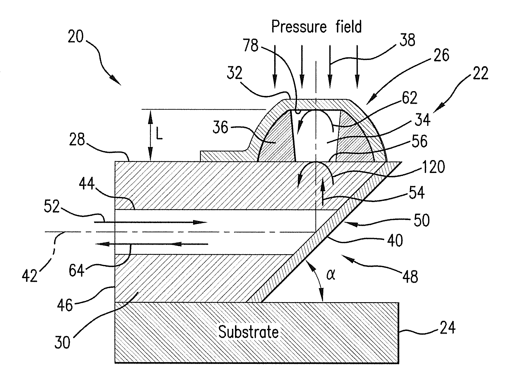
[0066]Referring to FIG. 2, an ultra-miniature pressure sensor system 20 includes a sensing head 22 which due to its cross-axial configuration is uniquely designed to permit surface mountability on a substrate 24. The sensing head 22 features an optical cavity structure 26, for example, a low finesse Fabry-Perot cavity structure, formed externally at the sidewall 28 of the optical fiber 30.

[0067]A diaphragm 32 of nanometer-scale-micrometer-scale thickness is covered on the air-filled optical cavity 34 of the optical cavity structure 26. The diaphragm 32 may be formed as a thin polymer layer or as a composite of a polymer diaphragm layer 58 and reflective diaphragm layer 60, shown in FIGS. 4H-4I, 5G, and 6D, as well as 8G-8H, and 9D-9F. The reflectivities of the polymer diaphragm layer 58 and the reflective diaphragm layer 60 are approximately 4% and 90%, respectively. As one example, a thin UV-curable polymer layer (e.g., negative photoresist) and a metal layer formed of Ag, Cu, Au, ...


PUM


Abstract

Ultra-miniature surface-mountable optical pressure sensor is constructed on an optical fiber. The sensor design utilizes an angled fiber tip which steers the optical axis of the optic fiber by 90°. The optical cavity is formed on the sidewall of the optic fiber. The optical cavity may be covered with a polymer-metal composite diaphragm to operate as a pressure transducer. Alternatively, a polymer-filled cavity may be constructed which does not need a reflective diaphragm. The sensor exhibits a sufficient linearity over the broad pressure range with a high sensitivity. The sensitivity of the sensor may be tuned by controlling the thickness of the diaphragm. Methods of batch production of uniform device-to-device optical pressure sensors of co-axial and cross-axial configurations are presented.

Description

REFERENCE TO RELATED APPLICATIONS[0001]This Utility patent application is a Continuation-In-Part of application Ser. No. 12 / 849,436 filed on 3 Aug. 2010, currently pending.[0002]The U.S. Government has certain rights to the invention. The work was funded by NSF Contract No. CMMI0644914.FIELD OF THE INVENTION[0003]The present invention relates to microsensors, and more in particular, to ultra-miniature pressure sensors formed on optical fibers.[0004]In overall concept, the present invention is directed to an ultra-miniature pressure sensor system in which a sensor element (sensing head) features an optical cavity structure formed on an optical fiber.[0005]Additionally, the present invention relates to a surface-mountable fiber-optic ultra-miniature optical pressure sensor that utilizes internal reflection at an angled fiber end surface to steer the optical axis by 90° in order to redirect the light travelling along the optical guide channel to impinge on the fiber sidewalls at a loca...

Claims


Application Information

Patent Timeline
IPC IPC(8): G01L9/00G02B1/12
CPCG01L9/0079G02B26/001G02B6/4214G02B6/262
Inventor YU, MIAOBAE, HYUNGDAEZHANG, XUMING
Owner UNIV OF MARYLAND
Why Eureka
Try Eureka