Bioreactor

Inactive Publication Date: 2017-11-14
HORSTMANN BERNHARD
View PDF11 Cites 1 Cited by
  • Summary
  • Abstract
  • Description
  • Claims
  • Application Information

AI Technical Summary

Benefits of technology

The technical effect of this patent text is to develop a bioreactor that is easy to build, has a high gas output, and is easy to maintain.

Problems solved by technology

Plug flow bioreactors of the type under discussion are comparatively complicated in their design and normally require a large number of additional buildings, for example, operations buildings, gas accumulators, etc.
The capital expenses of biogas plants operated in this way are correspondingly high.

Method used


Image

  • Bioreactor
  • Bioreactor
  • Bioreactor

Examples


Embodiment Construction

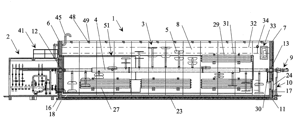
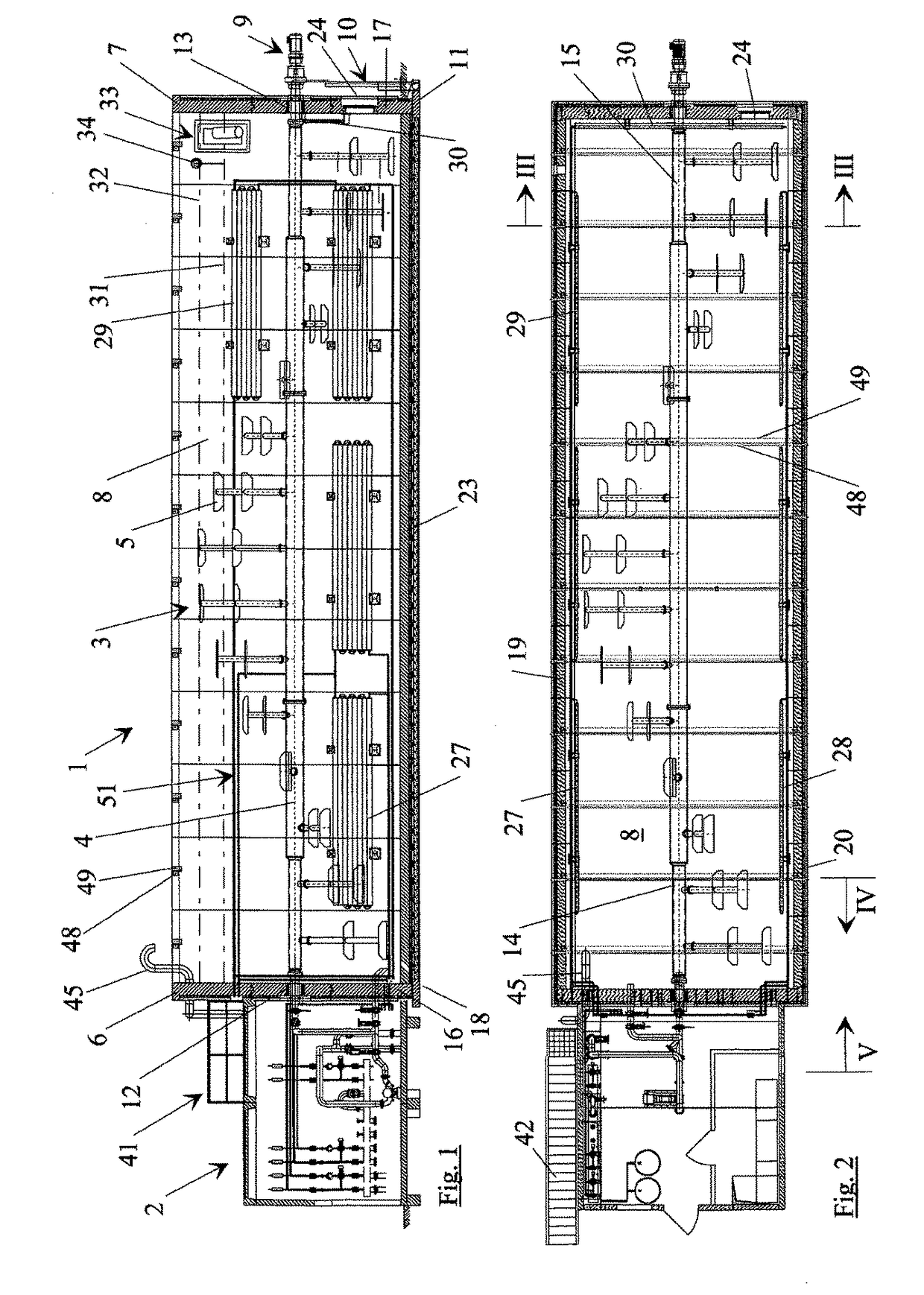
[0031]FIG. 1 is an off-center longitudinal section through a bioreactor 1 of one embodiment of the invention with an operations building 2 is connected to an end face of the bioreactor 1. The bioreactor is designed as a plug flow bioreactor with a long-shaft agitator 3, which has a central shaft 4 with a plurality of blades 5 that rotate spirally in the axial direction. The shaft 4 of the agitator 3 is supported on bearings exclusively in the two opposite end walls 6, 7. A center bearing is preferably deliberately dispensed with.

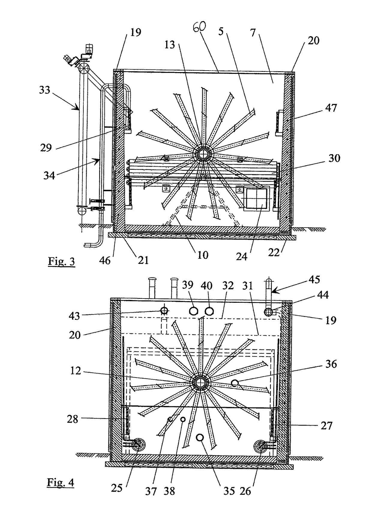
[0032]The shaft 4 passes through the wall 7 on the end opposite the operations building 2 and is connected to an electric motor drive 9 outside the fermentation chamber 8. The torque produced by the drive 9 is introduced into a foundation 11 via a triangular support structure 10 decoupled from the end wall 7 of the fermentation chamber 8, (see also FIG. 3).

[0033]The shaft 4, which is supported in the bearings 12, 13 in the walls 6, 7, is preferably divided i...


PUM


Abstract

Disclosed is a bioreactor, especially a plug flow bioreactor, including an agitator running along a longitudinal axis for thoroughly mixing a dry solid biomass that is to be outgassed in a fermentation chamber. In said bioreactor, an agitator shaft is mounted exclusively in two opposite end walls of the fermentation chamber while at least one free end of the agitator is connected to a drive unit outside the fermentation chamber.

Description

PRIORITY CLAIM[0001]This is a U.S. national stage of application No. PCT / DE2007 / 002190, filed on Dec. 6, 2007. Priority is claimed on German Application No. 10 2006 058 030.3, filed Dec. 7, 2006 and German Application No. 10 2007 014 417.4, filed Mar. 22, 2007, the contents of both of which are incorporated herein by reference.BACKGROUND OF THE INVENTION[0002]1. Field of the Invention[0003]The invention relates to a bioreactor, especially a plug flow bioreactor, which has a long-shaft agitator for thoroughly mixing a biomass with a high solids content that is to be degassed in a fermentation chamber.[0004]2. Description of the Prior Art[0005]The use of bioreactors in biogas plants is well known and has proven effective. In this connection, bioreactors are used for the fermentation of biowaste, green waste, food waste or the like, which has a high solids content, for example, more than 40%, without the addition of liquid manure. The resulting fermentation is dry mesophilic or thermop...

Claims


Application Information

Patent Timeline
IPC IPC(8): B01F15/06C12M1/06B01F7/04C12M1/107B01F7/00C05F17/02
CPCB01F15/066B01F7/00425B01F7/04C12M21/04C12M27/06C12M23/36C05F17/0223B01F2015/062C05F17/0217Y02P20/145C05F17/921C05F17/929B01F27/1144B01F27/70B01F35/93B01F2035/99Y02W30/40
Inventor SCHLUTER, THOMASHEITLAND, UWE
Owner HORSTMANN BERNHARD
Why Eureka
Try Eureka