Reduced offset voltage comparator system

Inactive Publication Date: 2007-07-05
MIROW FRED
View PDF4 Cites 0 Cited by
  • Summary
  • Abstract
  • Description
  • Claims
  • Application Information

AI Technical Summary

Benefits of technology

[0007]Mechanical stress, thermal stress, and other operating condition variations will not significantly effect performance because the reduced offset voltage comparator circuit frequently returns to the of

Problems solved by technology

The trimming technique has a drawback in that it is one time or a single shot operation and is therefore only provides compensation for the off

Method used


Image

  • Reduced offset voltage comparator system
  • Reduced offset voltage comparator system
  • Reduced offset voltage comparator system

Examples


Embodiment Construction

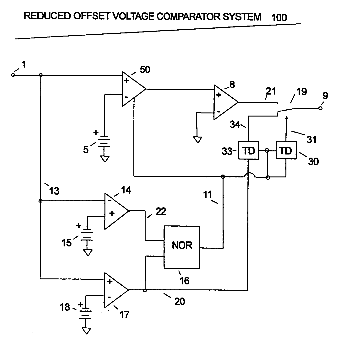
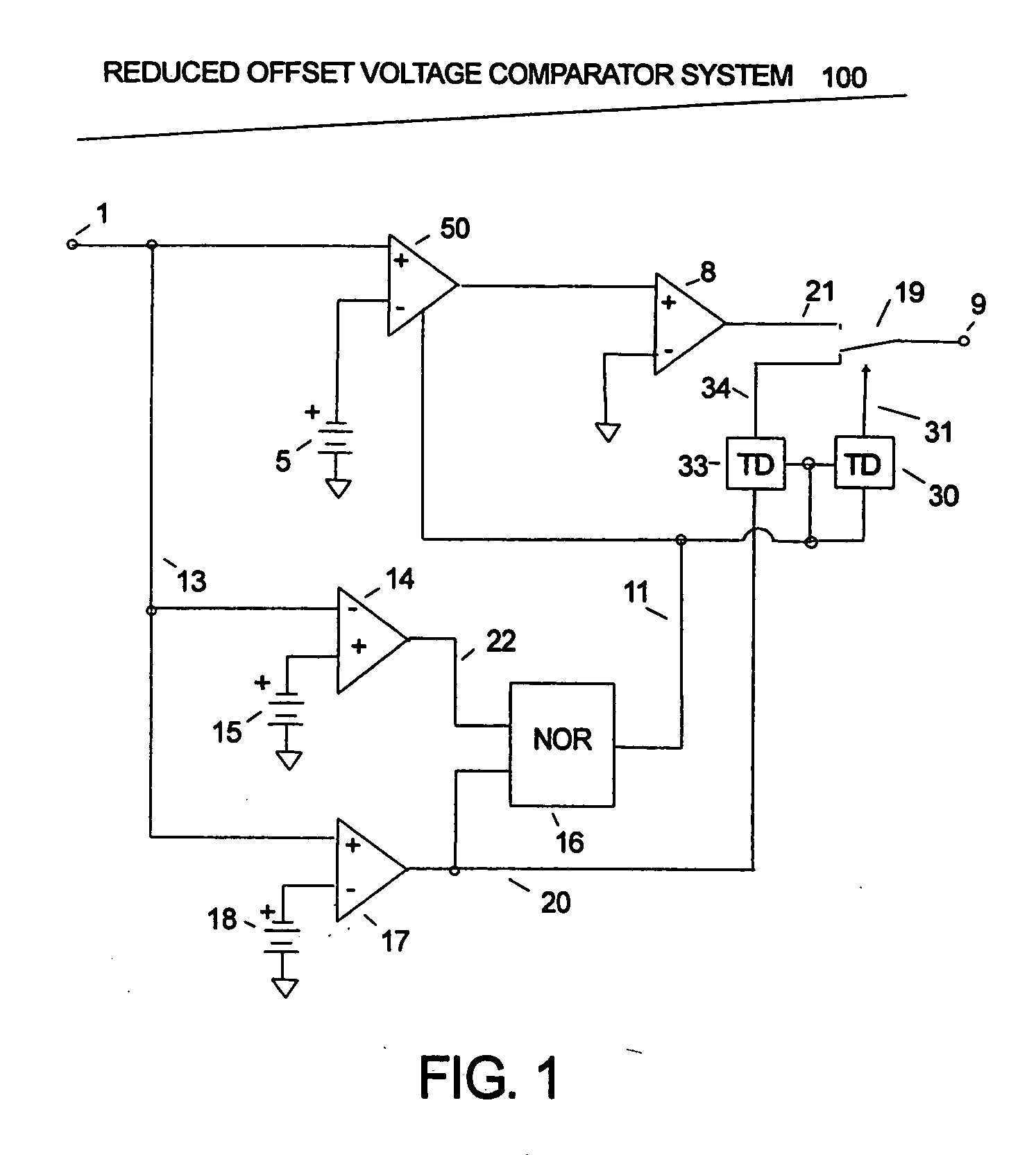
[0012]The Reduced Offset Voltage Comparator System FIG. 1 consist of three comparators 17, 14, and 8. The input signal at terminal 1 is applied to line 13. Comparators 14 has it's positive input connected to reference voltage 15 and it's negative input connected to line 13. Comparators 17 has it's negative input connected to reference voltage 18 and it's positive input connected to line 13.

[0013]Amplifier system 50 has it's negative input connected to reference voltage 5 and it's positive input connected to line 13. Comparators 8 has it's negative input connected to ground and it's positive input connected to the output of Amplifier system 50. Comparators 8 output is on line 21. Comparator 17 output is on line 20 and Comparator 14 output is on line 22. Line 20 and 22 are connected to the inputs of NOR gate 16. The output of NOR gate 16 on line 11 is low when either line 20 or 22 is high. Line 20 is also connected to the input of Time delay 33. Output terminal 9 is connected by switc...


PUM


Abstract

A method for comparing two signal with increased accuracy by using a reduced offset voltage comparator that has a offset zero mode and amplify mode. Additional comparators are used to indicate when the two signal are close in value. When the signal are close the reduced offset voltage comparator operation is changed from offset zero mode to amplify mode and the two signal are compared.

Description

CROSS-REFERENCE TO RELATED APPLICATIONS[0001]The benefits of filing this invention as Provisional application for patent “REDUCED OFFSET VOLTAGE COMPARATOR SYSTEM”, U.S. PTO Ser. No. 60 / 755,115 filed Dec. 31, 2005 by Fred Mirow are claimed.FIELD OF THE INVENTION[0002]The present invention relates to differential comparator systems with offset voltage reduction.BACKGROUND OF THE INVENTION[0003]A comparator, in its basic form, compares two input signals to determine which one is of higher magnitude. It outputs a high or low response depending on whether a first input is higher than a second input. Comparators have internal sources of errors that cause the output voltage level transitions to occur at a level different than when the input voltage levels transitions pass being equal. This error is referred to as the offset voltage.[0004]One current way of way of compensating for offset voltage is by trimming the device. In this method, a set of resistors is implanted on a chip. During th...

Claims


Application Information

Patent Timeline
IPC IPC(8): H03K5/22
CPCH03K5/24
Inventor MIROW, FRED
Owner MIROW FRED
Why Eureka
Try Eureka