

Plasma display apparatus
- Summary
- Abstract
- Description
- Claims
- Application Information
AI Technical Summary
Benefits of technology
Problems solved by technology
Method used
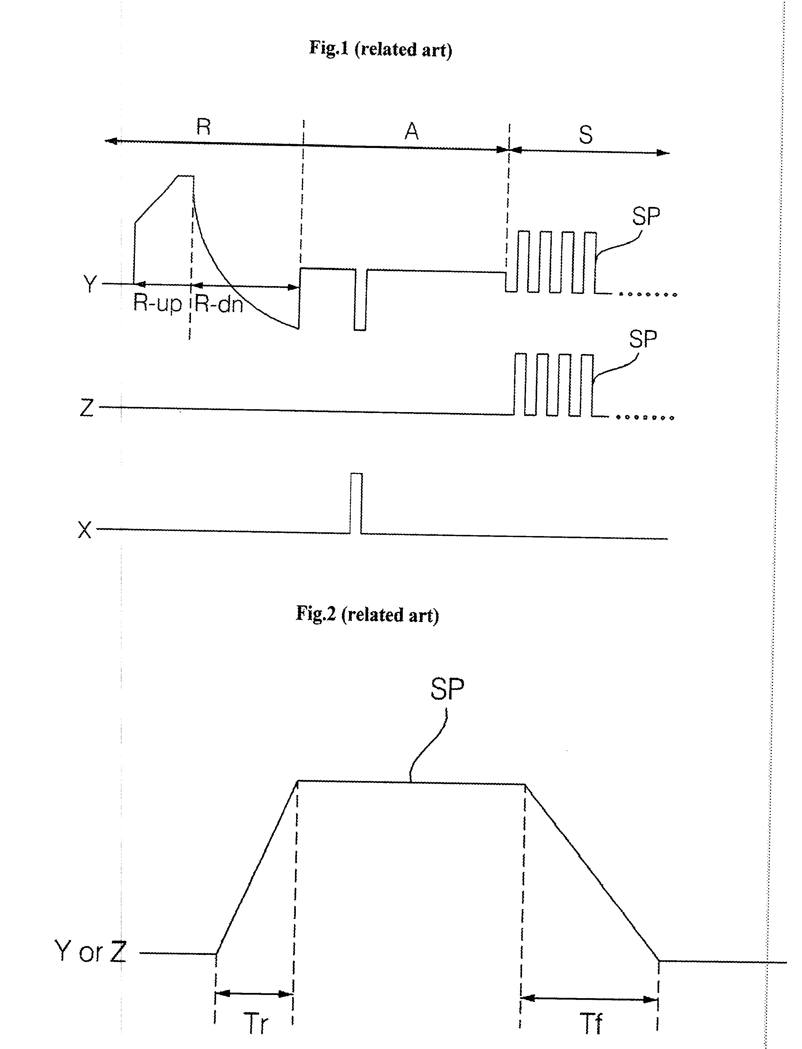
Image

Examples
first embodiment
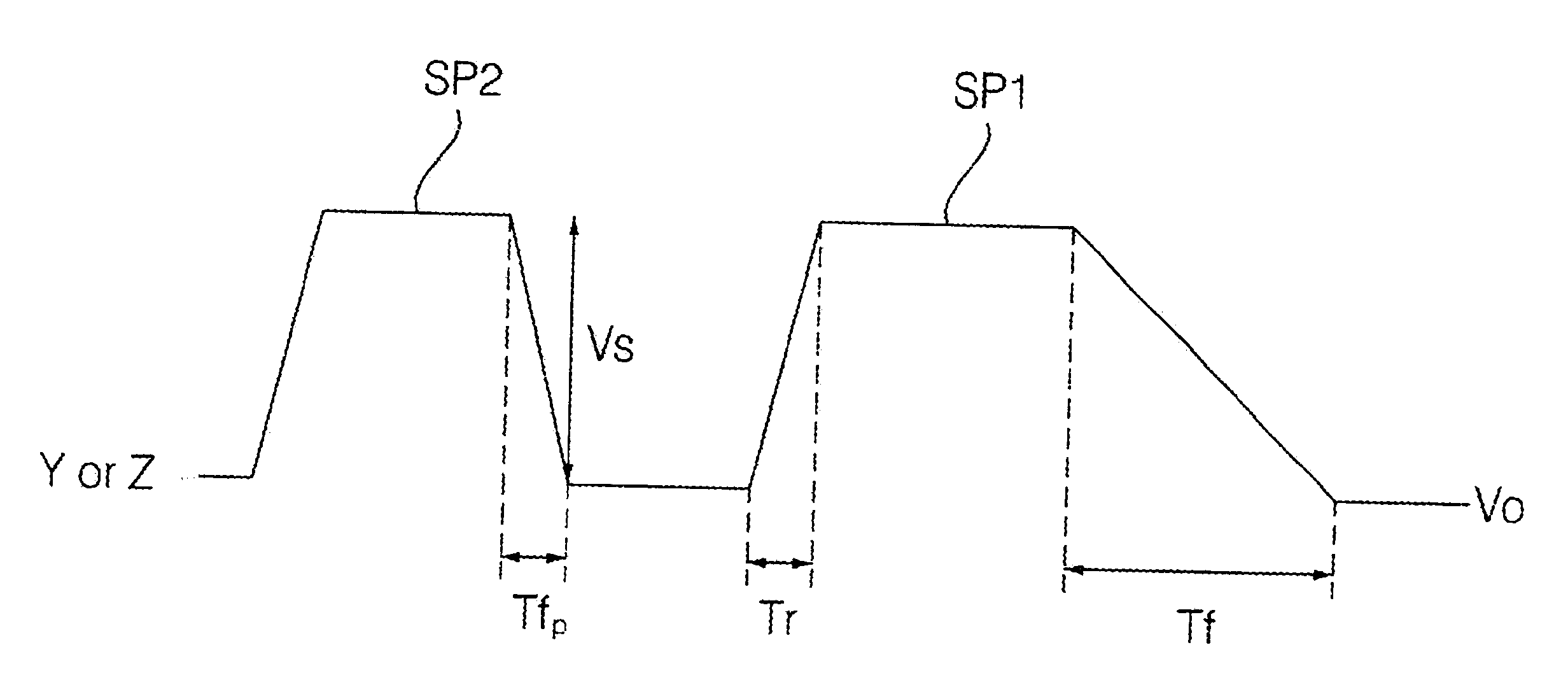
[0027]FIG. 3 illustrates a driving waveform of a plasma display apparatus according to the present invention.
[0028] The inventive plasma display apparatus includes a first electrode at an upper substrate, and a driver for applying a driving signal to the first electrode. By the driving waveform applied by the driver, discharge is generated and an image is displayed.
[0029] The first electrode can be any one of a scan electrode and a sustain electrode. The driver refers to a scan electrode driver or a sustain electrode driver corresponding to the first electrode.
[0030] The plasma display apparatus is driven with one frame divided into a plurality of subfields. Each of the subfields includes a reset period for initializing discharge cells of a whole screen, an address period for selecting the discharge cell, a sustain period for sustaining discharge of the selected discharge cell, and an erasure period for erasing wall charges within the discharge cell.
[0031] During the reset period...
second embodiment
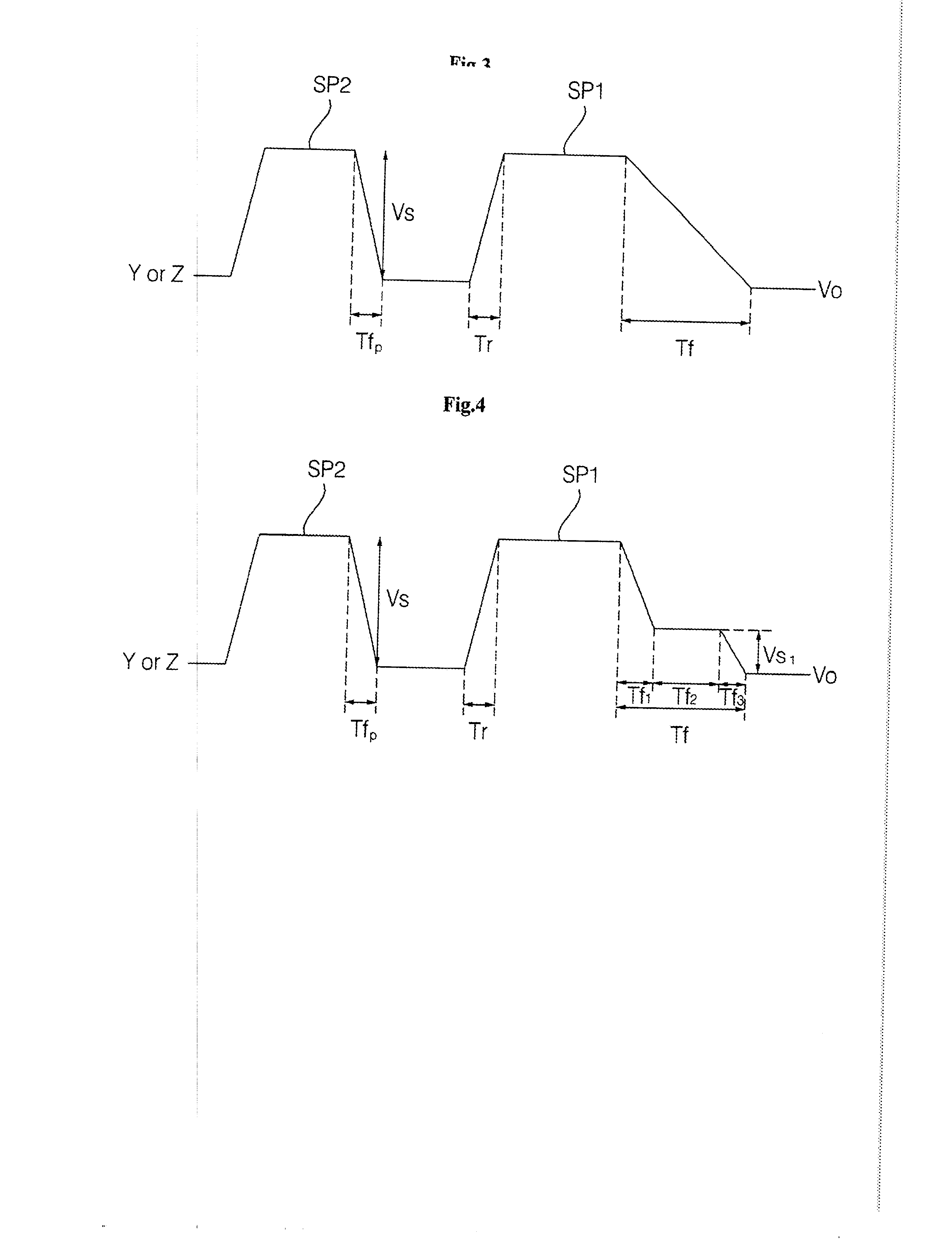
[0045]FIG. 4 illustrates a driving waveform of a plasma display apparatus according to the present invention.
[0046] Referring to FIG. 4, the plasma display apparatus according to the second embodiment of the present invention has a waveform whose, in one subfield, any one sustain pulse (SP1) reduces from high electric potential voltage (Vs) to first sustain voltage (Vs1), sustains the first sustain voltage for a predetermined time, and then reduces to low electric potential sustain voltage (Vo).
[0047] The above sustain pulse (SP1) is applied for the last sustain pulse in one subfield, for example, but without limitation to this, a plurality of sustain pulses just earlier than the last sustain pulse can be also constructed to have a format of the sustain pulse (SP1).
[0048] In the second embodiment of the present invention, a total falling time of the last sustain pulse is set to be longer than a failing time of any one sustain pulse (SP2) applied earlier than the last sustain pulse...
third embodiment
[0058]FIG. 5 illustrates a driving waveform of a plasma display apparatus according to the present invention.
[0059] Referring to FIG. 5, in the plasma display apparatus according to the third embodiment of the present invention, it is characterized to apply a driving waveform whose, in one subfield, upon fall, any one sustain pulse (SP1) falls along slopes having two or more steps, and its total falling time gets longer than a falling time of another sustain pulse (SP2) applied earlier than the sustain pulse (SP1).
[0060] The sustain pulse (SP1) is applied for the last sustain pulse as described above, for example, but without limitation to this, a plurality of sustain pulses just earlier than the last sustain pulse can be also constructed to have a format of the sustain pulse (SP1).
[0061] The first electrode is the scan electrode or the sustain electrode, and the sustain pulse (SP1) can be applied to all or any one of both electrodes.
[0062] Further, the slopes of the respective s...
PUM
| Property | Measurement | Unit |
|---|---|---|
| Time | aaaaa | aaaaa |
| Time | aaaaa | aaaaa |
| Time | aaaaa | aaaaa |
Abstract
Description
Claims
Application Information