Method, system, and program product for measuring audio video synchronization

a technology of audio video and program product, applied in the field of method, system and program product for measuring audio video synchronization, can solve the problems of inability to determine which syllables are being spoken, inability to determine the timing of speech, and limited applicability of the description of the paten

Inactive Publication Date: 2007-07-05
PIXEL INSTR CORP
View PDF30 Cites 15 Cited by
  • Summary
  • Abstract
  • Description
  • Claims
  • Application Information

AI Technical Summary

Benefits of technology

[0022] The invention provides methods, systems, and program products for identifying and locating muevs. As used herein the term “muev” is the contraction of MUtual EVent to mean an event occurring in an image, signal or data which is unique enough that it may be accompanied by another muev in an associated signal. Accordingly, an image muev may have a probability of matching a muev in an associated signal. For example in respect to the bat hitting the ball example above, the crack of the bat in the audio signal is a muev and the swing of the bat is also a muev. Clearly the two each have a probabili...

Problems solved by technology

If the program is produced with correct lip sync, that timing may be upset by subsequent operations, for example such as processing, storing or transmission of the program.
Unfortunately when there are no images of the mouth, there is no ability to determine which syllables are being spoken.
Consequently the applicability of the descriptions of the patents is limited to particular systems where various video timing information, etc. is utilized.
The detection and correlation of visual positioning of the lips corresponding to certain sounds and the audible presence of the corresponding sound is computationally intensive leading to high cost and complexity.
Slaney and Covell went on to describe optimizing thi...

Method used


Image

  • Method, system, and program product for measuring audio video synchronization
  • Method, system, and program product for measuring audio video synchronization
  • Method, system, and program product for measuring audio video synchronization

Examples


Embodiment Construction

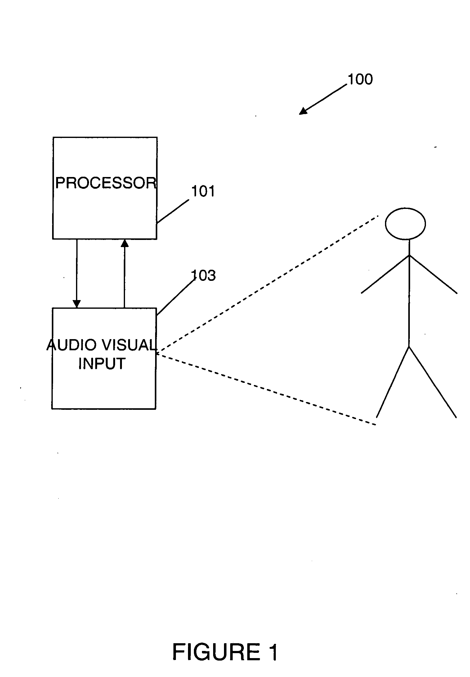
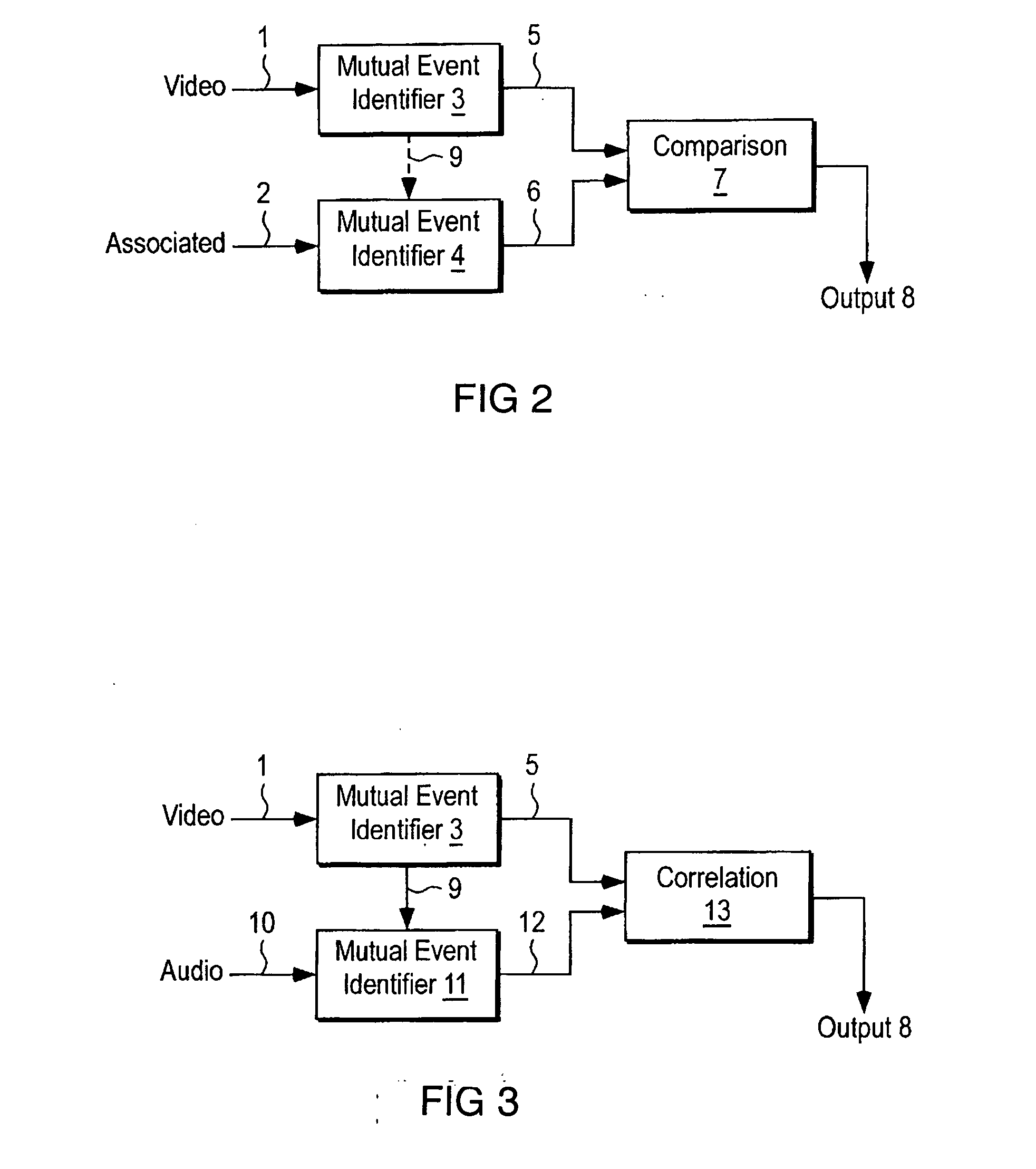
[0033] The preferred embodiment of the invention has an image input, an image mutual event identifier which provides image muevs, and an associated information input, an associated information mutual event identifier which provides associated information muevs. The image muevs and associated information muevs are suitably coupled to a comparison operation which compares the two types of muevs to determine their relative timing. In particular embodiments of the invention, muevs may be labeled in regard to the method of conveying images or associated information, or may be labeled in regard to the nature of the images or associated information. For example video muev, brightness muev, red muev, chroma muev and luma muev are some types of image muevs and audio muev, data muev, weight muev, speed muev and temperature muev are some types of associated muevs which may be commonly utilized.

[0034]FIG. 1 shows the preferred embodiment of the invention wherein video conveys the images and an...


PUM


Abstract

Method, system, and program product for measuring audio video synchronization. This is done by first acquiring audio video information into an audio video synchronization system. The step of data acquisition is followed by analyzing the audio information, and analyzing the video information. In this phase audio and video information is analyzed, decision boundaries for Audio and Video MuEv-s are determined, and related Audio and Video MuEv-s are correlated. In Analysis Phase Audio and Video MuEv-s are calculated from the audio and video information, and the audio and video information is classified into vowel sounds including AA, EE, OO, silence, and unclassified phonemes This information is used to determine and associate a dominant audio class in a video frame. Matching locations are determined, and the offset of video and audio is determined.

Description

BACKGROUND OF INVENTION [0001] 1. Field of the Invention [0002] The invention relates to the creation, manipulation, transmission, storage, etc. and especially synchronization of multi-media entertainment, educational and other programming having at least video and associated information. [0003] 2. Background Art [0004] The creation, manipulation, transmission, storage, etc. of multi-media entertainment, educational and other programming having at least video and associated information requires synchronization. Typical examples of such programming are television and movie programs. Often these programs include a visual or video portion, an audible or audio portion, and may also include one or more various data type portions. Typical data type portions include closed captioning, narrative descriptions for the blind, additional program information data such as web sites and further information directives and various metadata included in compressed (such as for example MPEG and JPEG) s...

Claims


Application Information

Patent Timeline
IPC IPC(8): H04N17/02H04N9/475H04N7/52
CPCG06K9/00335H04N5/04H04N21/44008H04N21/2368H04N21/4341H04N17/00G06V40/20
Inventor COOPER, J. CARLVOJNOVIC, MIRKO DUSANROY, JIBANANANDAJAIN, SAURABHSMITH, CHRISTOPHER
Owner PIXEL INSTR CORP
Why Eureka
Try Eureka