Variable focus lens having a plurality of protrusions at one end of fluid chamber

a variable focus lens and fluid chamber technology, applied in the field of variable focus lenses, can solve the problems of fluid lens not being usable, reducing productivity, drawbacks of conventional variable focus lenses, etc., and achieve the effect of preventing the formation of bubbles

Inactive Publication Date: 2007-07-05
SAMSUNG ELECTRO MECHANICS CO LTD
View PDF1 Cites 6 Cited by
  • Summary
  • Abstract
  • Description
  • Claims
  • Application Information

AI Technical Summary

Benefits of technology

[0023]The present invention has been made to solve the foregoing problems of the prior art and therefore an object of certain embodiments of the present invention is to provide a variable focus lens which has a plurality of protrusions formed on one end of a chamber to prevent formation of bubbles.

Problems solved by technology

However, the conventional variable focus lens has drawbacks as shown in FIG. 4.
The fluid lens is not usable if such a bubble is formed.
To prevent such a problem, the lens can be assembled inside the liquid, which however does not completely suppress the formation of the bubbles, diminishes productivity and hinders mass production of lens.

Method used


Image

  • Variable focus lens having a plurality of protrusions at one end of fluid chamber
  • Variable focus lens having a plurality of protrusions at one end of fluid chamber
  • Variable focus lens having a plurality of protrusions at one end of fluid chamber

Examples


Embodiment Construction

[0042]Preferred embodiments of the present invention will now be described in detail with reference to the accompanying drawings.

[0043]First, FIG. 7 illustrates a configuration of a variable focus lens 100 according to an embodiment of the present invention.

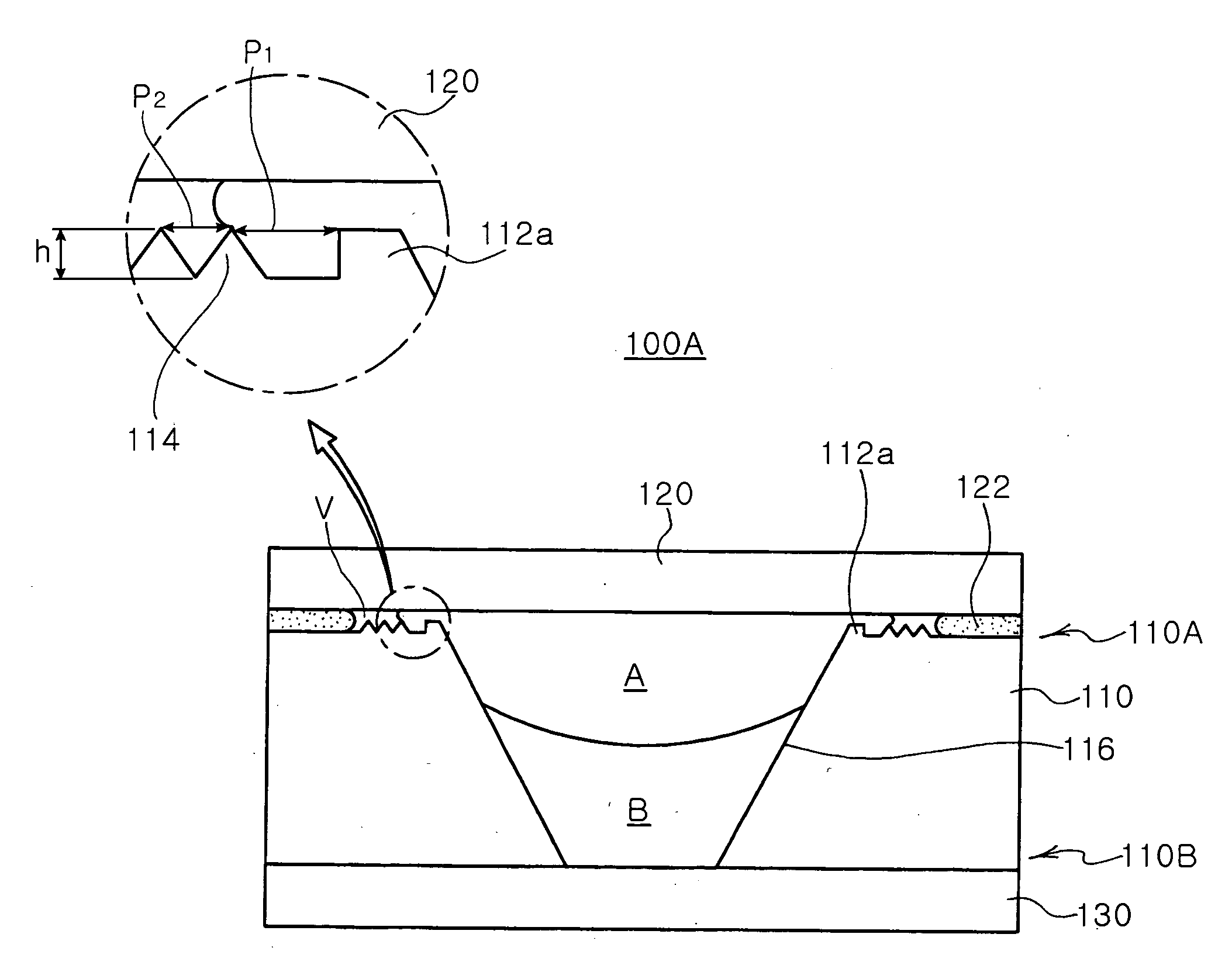
[0044]The variable focus lens 100 includes a chamber wall 110 forming a cylindrical inner space with a first bump or protrusion 112, a second protrusion 114 and two third protrusions 115 formed on one end thereof, an upper transparent plate 120 attached to an upper end 110A of the chamber wall 110 with a predetermined interval G in between and a lower transparent plate 130 attached to a lower end 110B of the chamber wall 110.

[0045]Here, the first protrusion 112 has a rectangular section and each of the second and third protrusions 114 and 115 has an inverted triangular section. Thus, three grooves are formed by the first protrusion 112, the second protrusion 114 and the third protrusion 115.

[0046]At this time, the upper transpare...


PUM


Abstract

The present invention relates to a variable focus lens including a fluid chamber containing first and second fluids which are non-miscible and have different refractive indices, the fluid chamber having a plurality of protrusions formed along a circumference of one open end thereof. The variable focus lens also includes a transparent plate attached to the open end of the chamber via a sealing with a predetermined interval from the protrusions. The variable focus lens further includes a first electrode disposed inside the chamber to act on the first fluid and a second electrode disposed inside the chamber and is insulated from the first fluid. The invention allows an easy manufacturing process without bubble formation, and eliminates entry and formation of bubbles due to external changes such as in temperature and pressure, thereby allowing good performance of the lens regardless of external environmental changes.

Description

CLAIM OF PRIORITY[0001]This application claims the benefit of Korean Patent Application No. 2005-133804 filed on Dec. 29, 2005, in the Korean Intellectual Property Office, the disclosure of which is incorporated herein by reference.BACKGROUND OF THE INVENTION[0002]1. Field of the Invention[0003]The present invention relates to a variable focus lens, and more particularly, to a variable focus lens which has a plurality of protrusions formed at one end of a chamber to prevent bubble formation and absorbs volume change of fluid due to changes in external environment such as temperature and pressure to eliminate entry or formation of bubbles, thereby functioning well as a lens regardless of external changes.[0004]2. Description of the Related Art[0005]In general, a camera is equipped with a plurality of lenses and is configured to adjust optical focus distance by driving the lenses respectively to vary the relative distances thereof. Due to the miniaturization of optical devices such as...

Claims


Application Information

Patent Timeline
Patent Type & Authority Applications(United States)
IPC IPC(8): G02B3/12
CPCG02B26/005G02B3/14G02B3/12
Inventor OH, BYUNG DOPARK, YOUNG KYU
Owner SAMSUNG ELECTRO MECHANICS CO LTD
Why Eureka
Try Eureka