Decorative lighting device

a lighting device and decorative technology, applied in the direction of coupling device connection, lighting and heating apparatus, transportation and packaging, etc., can solve the problems of increasing the temperature of the decorative lighting device, not meeting the safety standards of the conventional decorative lighting device b>1/b>, and needing improvement, etc., to achieve enhanced heat isolation and waterproof

Inactive Publication Date: 2007-07-05
LIN VINCENT
View PDF6 Cites 10 Cited by
  • Summary
  • Abstract
  • Description
  • Claims
  • Application Information

AI Technical Summary

Benefits of technology

[0010] Therefore, the object of the present invention is to provide a decorative lighting device that has enhanced heat-isolation and waterproof effects so as to ensure safety thereof.
[0011] According to the present invention, there is provided a decorative lighting device that includes a light-emitting unit, a holding unit, and a light-transmissive body. The light-emitting unit includes a plug-in base and a light bulb. The plug-in base is made from an insulating material, and includes upper and lower bodies disposed opposite to each other along an axis. The upper body includes an end wall surface that has a cavity extending towards the lower body to define a bulb-receiving space. The lower body includes two lateral guiding walls which are opposite to each other in a transverse direction relative to the axis. The light bulb has a lower bulb portion, and first and second lead-in wires which extend downwardly and outwardly of the lower bulb portion, and which are configured such that when the lower bulb portion is inserted into the bulb-receiving space, the first and second lead-in wires extend downwardly and outwardly of the upper body of the plug-in base to be located between the two lateral guiding walls in the transverse direction. The holding unit is made from an insulating material, and includes inner and outer surrounding walls, an annular connecting wall, and two electrical terminals. The inner surrounding wall extends downwardly along the axis to terminate at an inner surrounding edge, and has inner and outer wall surfaces opposite to each other in radial directions relative to the axis. The outer surrounding wall extends downwardly along the axis to terminate at an outer surr...

Problems solved by technology

However, as the electric current flowing through the conventional decorative lighting device 1 increases, heat dissipation increases in a square function, resulting in an increase in temperature that ...

Method used


Image

  • Decorative lighting device
  • Decorative lighting device
  • Decorative lighting device

Examples


Embodiment Construction

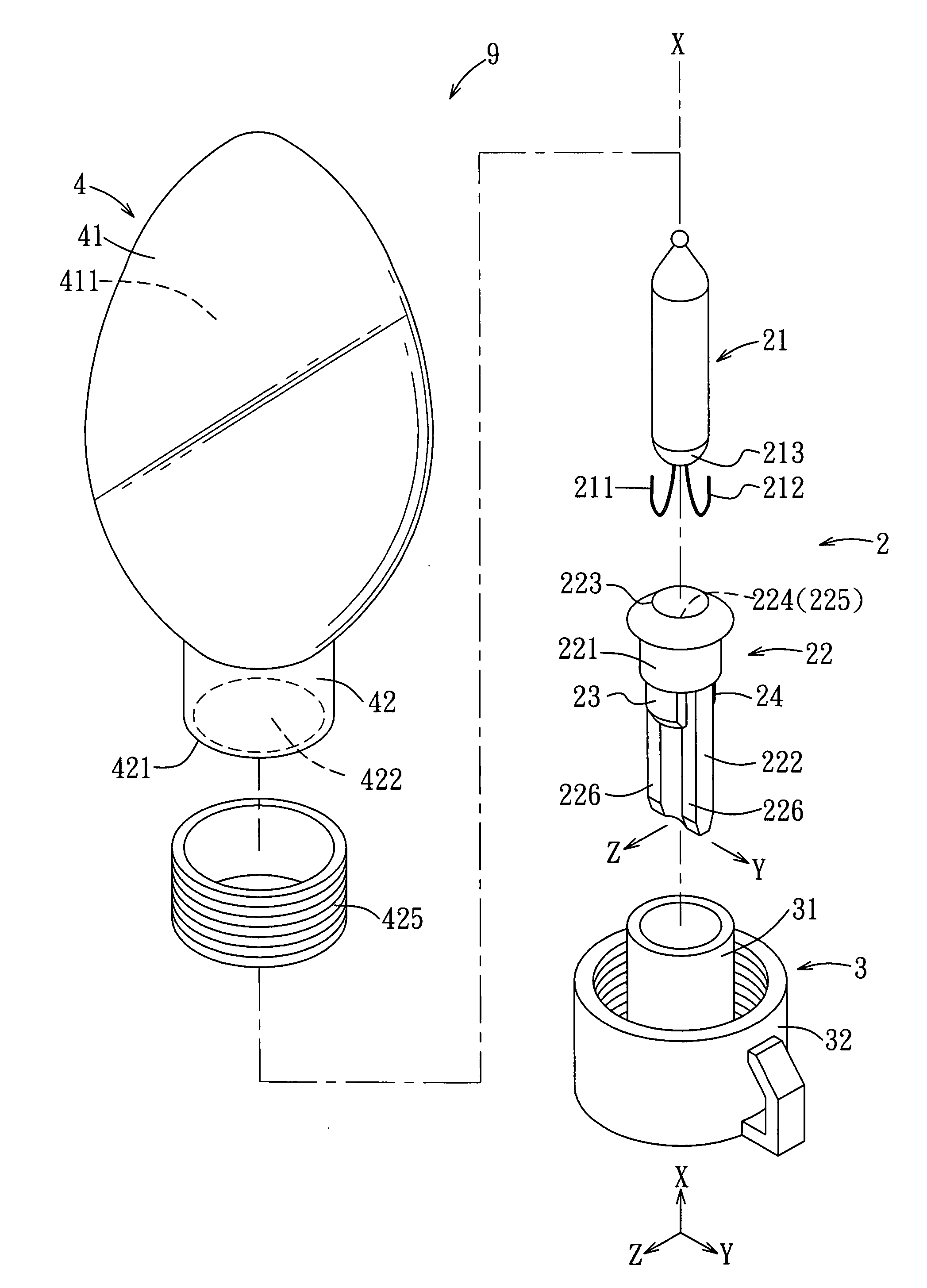
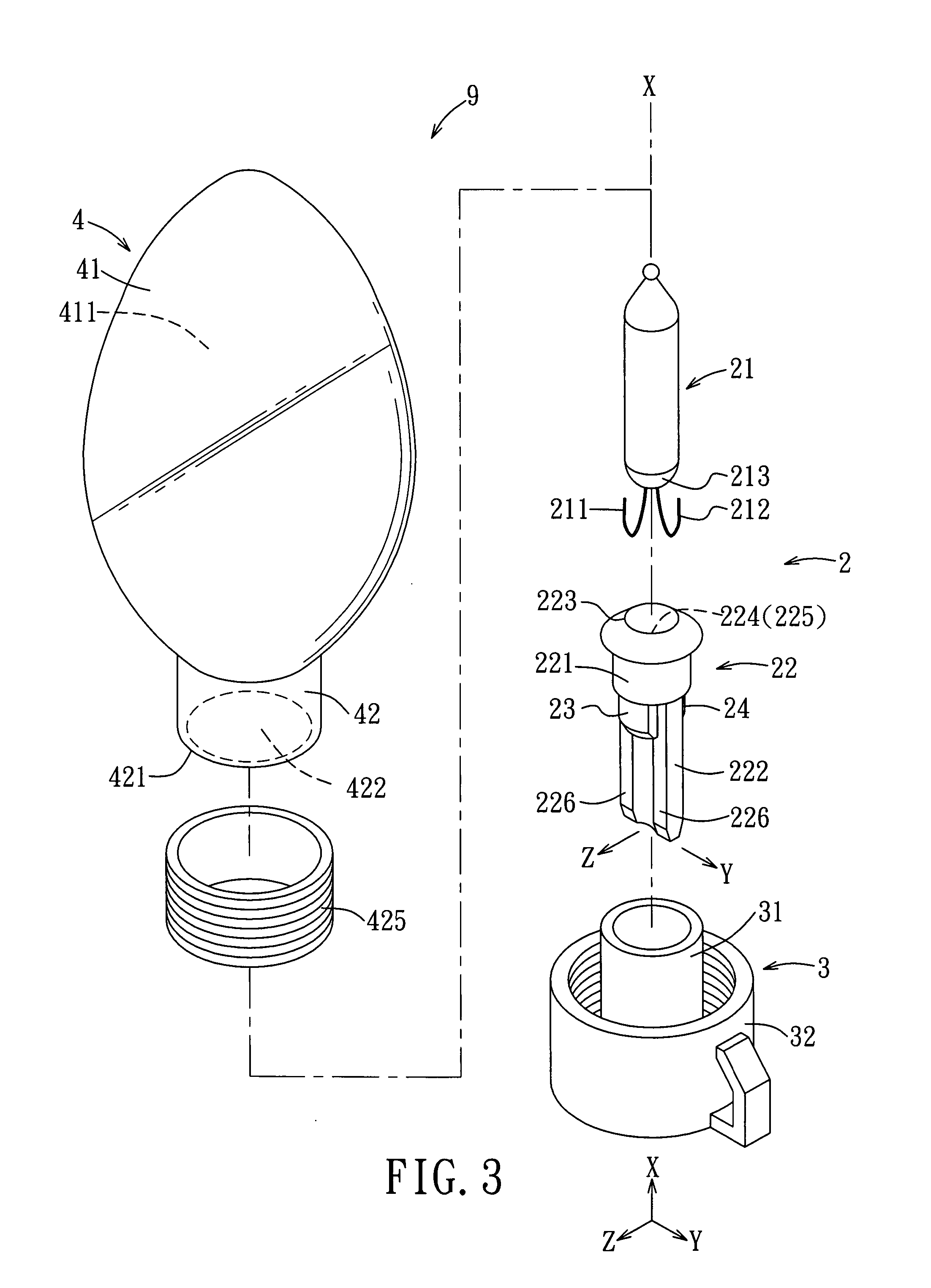
[0019] As shown in FIG. 3 and FIG. 4, the preferred embodiment of a decorative lighting device 9 according to the present invention includes a light-emitting unit 2, a holding unit 3, and a light-transmissive body 4.

[0020] The light-emitting unit 2 includes a plug-in base 22 and a light bulb 21. The plug-in base 22 is made from an insulating material (e.g., plastic), and includes upper and lower bodies 221, 222 disposed opposite to each other along an axis (X). The upper body 221 includes an end wall surface 223 that has a cavity 224 extending towards the lower body 222 to define a bulb-receiving space 225. The lower body 222 includes two lateral guiding walls 226 (only one is shown in FIG. 4) which are opposite to each other in a first transverse direction (Y) relative to the axis (X). The light bulb 21 has a lower bulb portion 213, and first and second lead-in wires 211, 212 which extend downwardly and outwardly of the lower bulb portion 213, and which are configured such that wh...


PUM


Abstract

A decorative lighting device includes: a light-emitting unit; a holding unit which includes an inner surrounding wall that has an outer wall surface, an outer surrounding wall that has a surrounding engaging surface spaced apart from the outer wall surface with a surrounding clearance, and an annular connecting wall that attaches the outer surrounding wall to the outer wall surface to form a surrounding abutment surface confronting the surrounding clearance; and a light-transmissive housing which includes an annular neck portion that terminates at an annular edge, that has inner and outer annular surfaces, and that is configured such that once the annular edge is brought to abut against the surrounding abutment surface, the outer annular surface is engaged with the surrounding engaging surface, while the inner annular surface is spaced apart from the outer wall surface to thereby cut off creepage of intruding extraneous water into the inner surrounding wall.

Description

BACKGROUND OF THE INVENTION [0001] 1. Field of the Invention [0002] The invention relates to a decorative lighting device, more particularly to a decorative lighting device that has enhanced heat-isolation and waterproof effects. [0003] 2. Description of the Related Art [0004] As shown in FIG. 1 and FIG. 2, a conventional decorative lighting device 1 includes a light-emitting unit 11, a holding unit 12, and two electric wires 13. [0005] The light-emitting unit 11 includes a plug-in base 112 and a light bulb 111. The plug-in base 112 is made from an insulating material, and includes upper and lower bodies 113, 114 disposed opposite to each other along an axis (X1). The upper body 113 defines a bulb-receiving space 118. The lower body 114 includes a lateral guiding wall 116 extending downwardly from the upper body 113 along the axis (X1). The light bulb 111 has a lower bulb portion 117, and two lead-in wires 115 which extend downwardly and outwardly of the lower bulb portion 117, and ...

Claims


Application Information

Patent Timeline
IPC IPC(8): F21V15/00
CPCF21S4/001F21V3/00Y10S362/806F21V19/0005F21V17/06F21S4/10
Inventor LIN, VINCENT
Owner LIN VINCENT
Why Eureka
Try Eureka