Connector

a technology of connecting rods and connectors, applied in the direction of coupling device connections, coupling protective earth/shielding arrangements, electrical appliances, etc., can solve the problems of complicated connectors, difficult design, and further a measure of crosstalk, so as to achieve the effect of easy handling

Inactive Publication Date: 2007-07-05
JAPAN AVIATION ELECTRONICS IND LTD
View PDF13 Cites 49 Cited by
  • Summary
  • Abstract
  • Description
  • Claims
  • Application Information

AI Technical Summary

Benefits of technology

[0005] It is therefore an object of this invention to provide a connector that can easil

Problems solved by technology

The foregoing connector is complicated because there are many assembly processes during the manufacture.
Further, when the lengths of lines for transmitting signals are not physically equal among the contact modules, a difficult design is req

Method used


Image

  • Connector
  • Connector
  • Connector

Examples


Embodiment Construction

[0025] Referring to the drawings, a connector according to one embodiment of this invention will be described. This connector is used for transmission of high-speed differential signals.

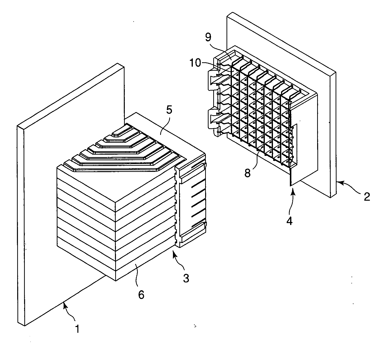
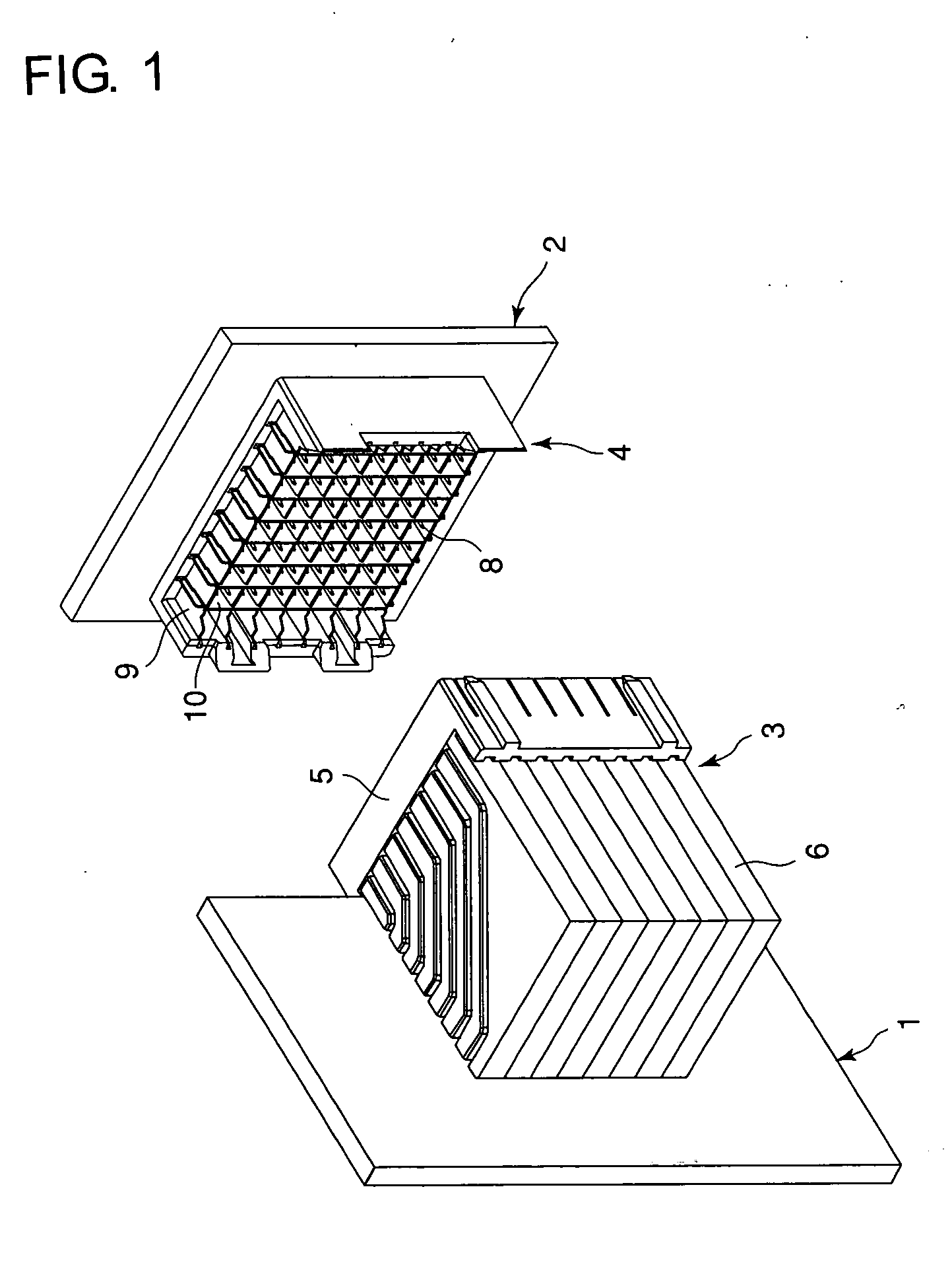
[0026] Referring to FIGS. 1 and 2, there are shown a plug connector 3 press-fitted to a backplane 1 and a receptacle connector 4 press-fitted to a midplane 2. The plug connector 3 and the receptacle connector 4 can be fitted and connected together.

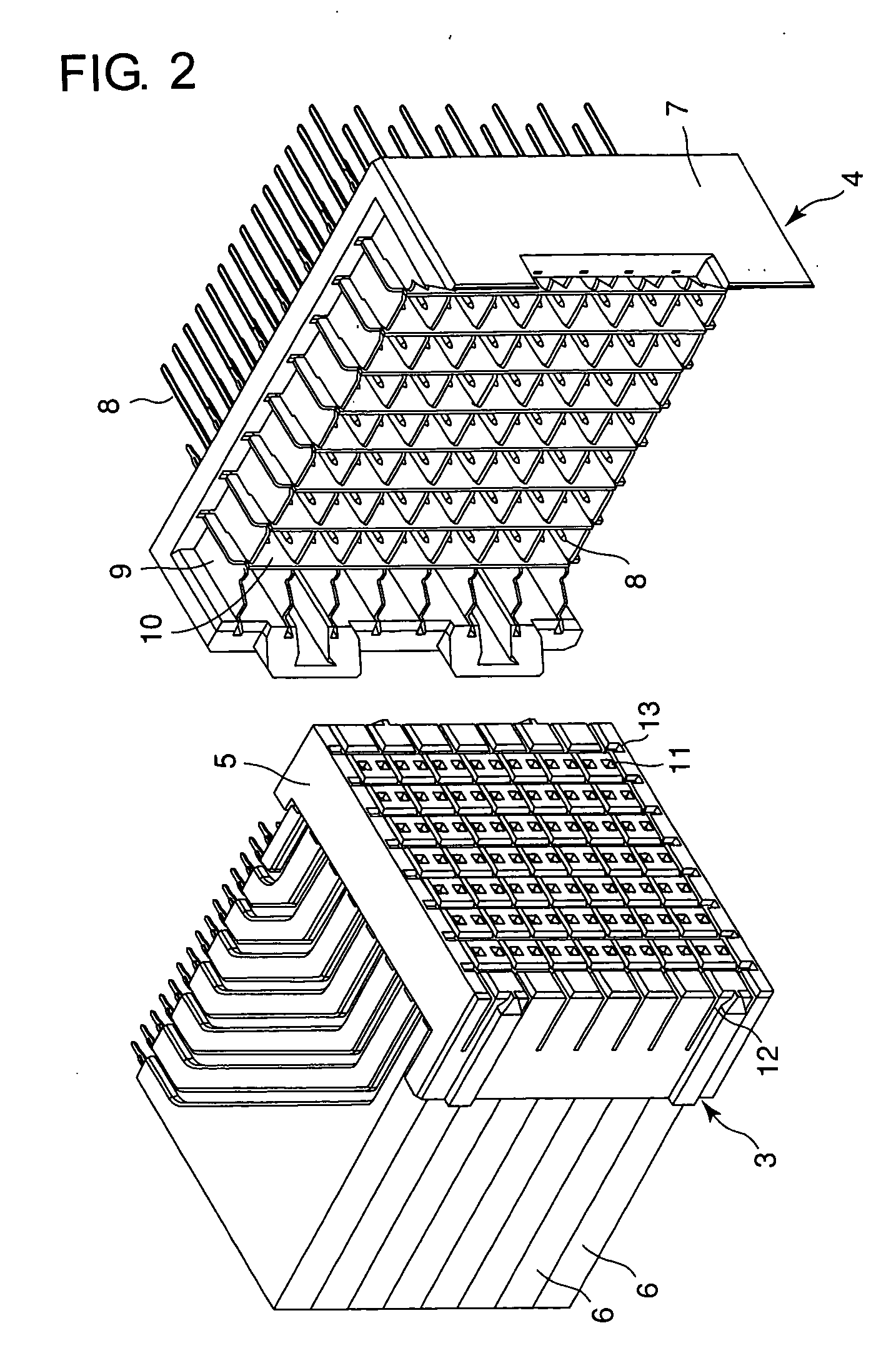
[0027] The plug connector 3 comprises an insulating front housing 5 and a plurality of plate-shaped contact modules 6 attached to the front housing 5 in parallel to each other. The receptacle connector 4 comprises an insulating housing 7, a number of, specifically 98, conductive pin headers (7 in vertical direction and 14 in lateral direction) 8 held by the housing 7, eight first ground plates 9 each arranged in the housing 7 in the lateral direction, and eight second ground plates 10 each arranged in the housing in the vertical direction. The first and s...


PUM


Abstract

A connector having juxtaposed contact modules (6). In each contact module, signal contacts (16), a first ground plate (14), and a second ground plate (15) are held by an insulator (28). The first and second ground plates comprise plate sections (14a, 15a) each having a first surface and a second surface on the opposite side of the first surface, and the first surfaces face each other. Pairs of protrusions (14b, 15b) are formed at intervals on the second surfaces of the plate sections. The first and second ground plates are molded in the insulator and integrated together. The insulator has recesses (29) corresponding to the intervals of the protrusions and signal contacts are disposed in the recesses.

Description

TECHNICAL FIELD [0001] This invention relates to a connector having a plurality of juxtaposed contact modules each configured such that a ground plate partitions between adjacent signal contacts. BACKGROUND ART [0002] Even in the field where electrical signals have high frequencies, there is a demand for connecting between printed boards by a connector. The subjects required in this case are crosstalk reduction, impedance matching, measures against deviation in propagation time between signals, and so on. [0003] This type of connector is disclosed, for example, in Japanese Unexamined Patent Publication No. H6-325829 and Japanese Patent No. 2537698 and includes a plurality of contact modules each configured such that contacts are held by a mold component. In the manufacture of the contact module, there is a case where the contacts are molded-in with the insulator or a case where the mold component having grooves each with a shape resembling the contact is formed and the contacts are ...

Claims


Application Information

Patent Timeline
IPC IPC(8): H01R13/648H01R13/514H01R13/658H01R13/6471H01R13/6474H01R13/6477H01R13/6585
CPCH01R13/514H01R13/6587H01R13/65807
Inventor NAKADA, KOUJI
Owner JAPAN AVIATION ELECTRONICS IND LTD
Why Eureka
Try Eureka