

Automatic project management application
a project management and project technology, applied in the field of computer-implemented project management, can solve the problems of tedious activity reporting, easy fraud, and easy error-pron
- Summary
- Abstract
- Description
- Claims
- Application Information
AI Technical Summary
Benefits of technology
Problems solved by technology
Method used
Image

Examples
embodiment 1
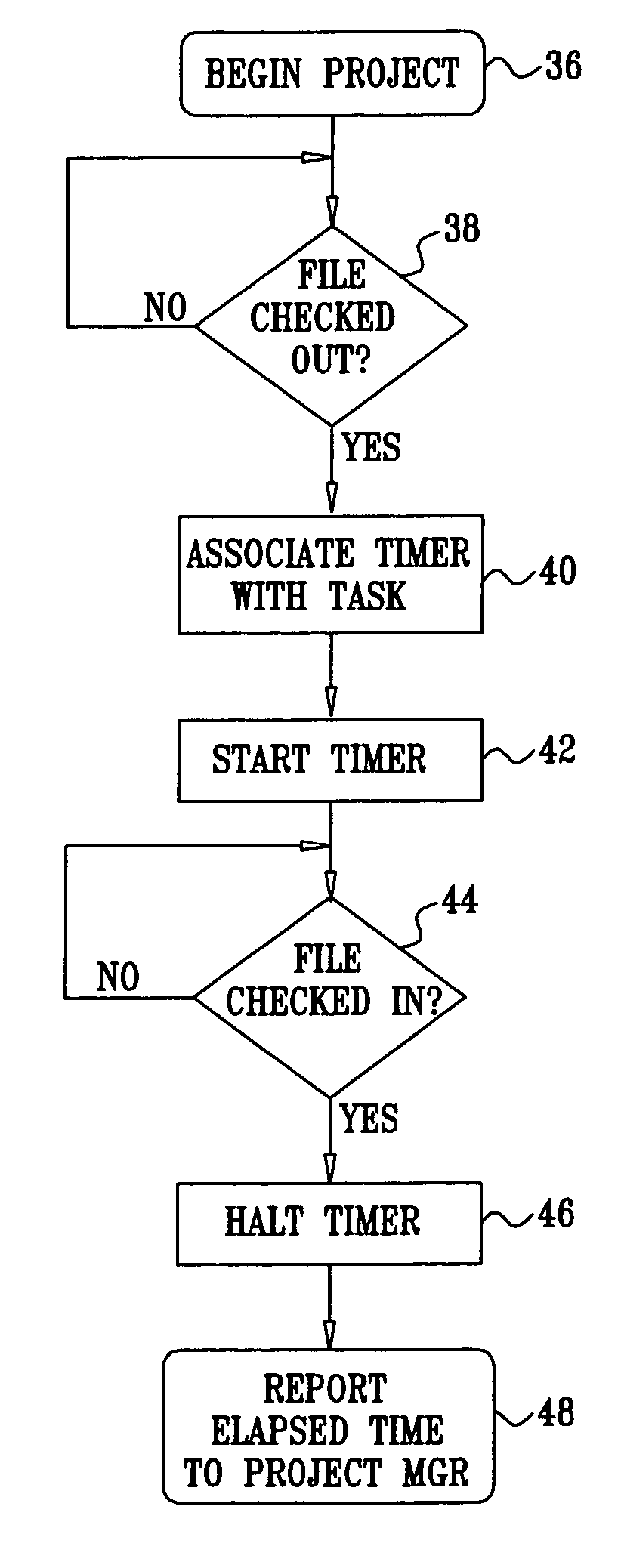
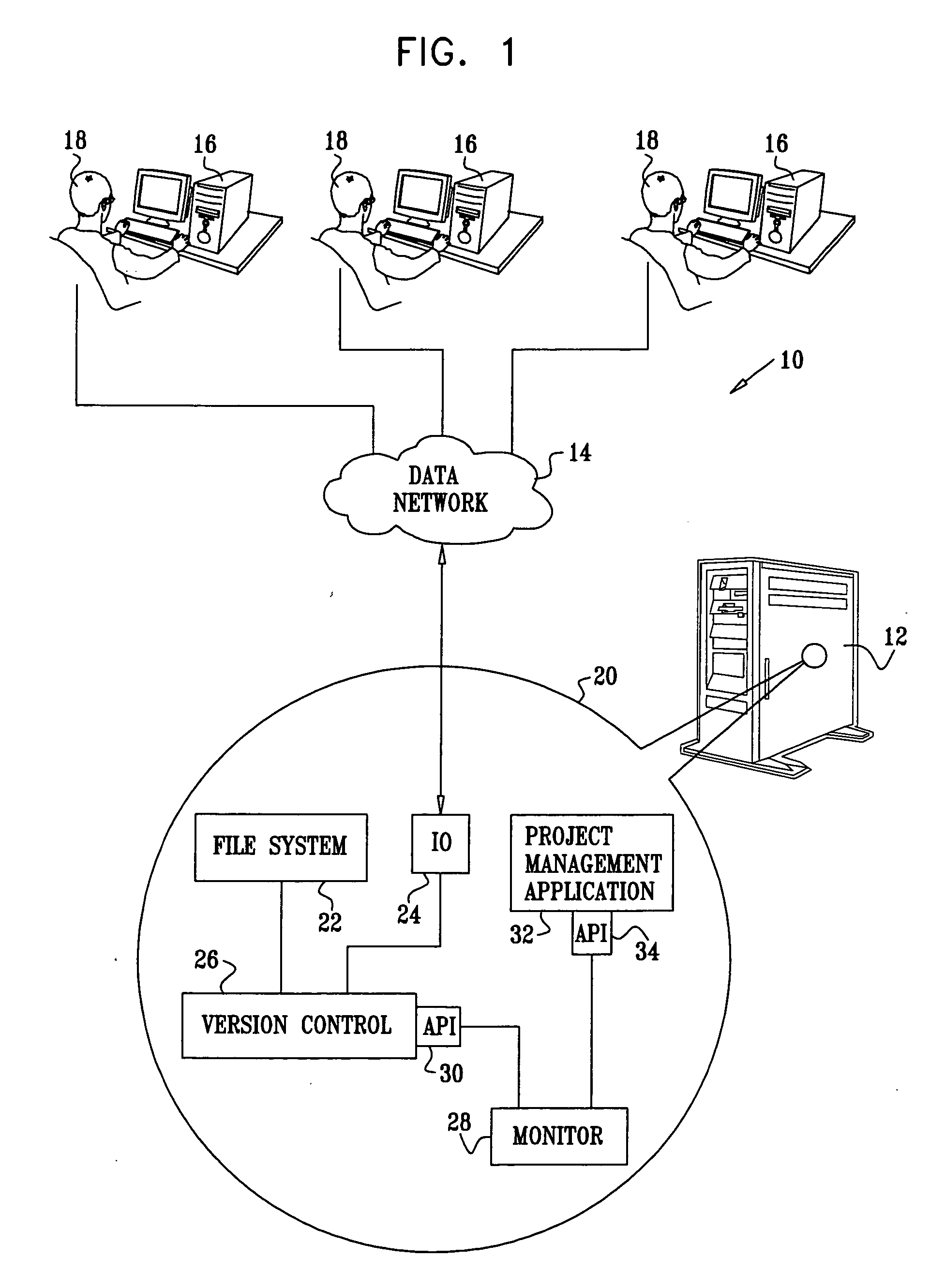
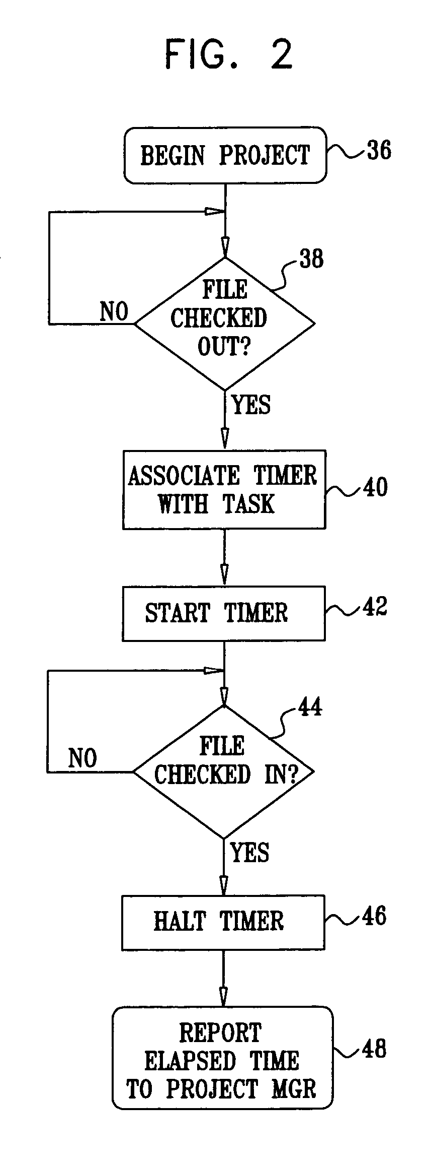
[0032] The system 10 typically includes a memory 20, which may be localized in the server 12 or distributed among the server 12 and the computers 16 in many combinations, as is known in the art. In any case the memory 20 contains objects corresponding to the following functional blocks, which are responsive to activities of the users 18. A file system 22 contains various data elements, e.g., directories and files, which are accessed during project-related activities of the users 18. These accesses are mediated conventionally by the server's operating system, shown as an I / O block 24, and moderated by a generic version control application 26. A monitor 28, executing automatically, for example as a daemon or other background process, constantly monitors the activities of the version control application 26, which are exposed via an application programming interface 30 (API). A project management application 32, which is responsible for accumulating the activities of the users 18, recei...
embodiment 2
[0041] Reference is now made to FIG. 3, which is a block diagram of a portion of the system 10 (FIG. 1), in which the memory 20 is provided with functional objects enabling multiple projects to be managed concurrently in accordance with an alternate embodiment of the invention.
[0042] In this embodiment the project management application 32 simultaneously supports two source control environments, represented as version control applications 50, 52. Adapters 54, 56 provide interfaces between the project management application 32 and the version control applications 50, 52, respectively. The adapters 54, 56 are programmed to monitor activities of the users 18 (FIG. 1) with respect to files checked out via the version control applications 50, 52, and to trigger the task-related steps caused by check-in and check-out as described in the discussion of FIG. 2. Adapters 58, 60 provide respective links between the project management application 32 and two subsidiary project management applic...
embodiment 3
[0050] In a one-to-many situation, a single resource is shared by more than one project. Conventionally, the manager of each project would manage the resource independently of the other mangers. Indeed, a project manager might be oblivious that one of its resources was being utilized by other projects, except that such a resource might be reported as unavailable, e.g., resulting from a file being locked. This difficulty is solved by expansion of the functions of the monitor 28 (FIG. 1). Hooks are provided that provide each project manager with information about the use of resources by other project manager.
[0051] Reference is now made to FIG. 5, which is a block diagram illustrating a system 80 for automatically and concurrently tracking project-related activities by multiple project managers in accordance with an alternate embodiment of the invention. Any number of projects, represented by a first project and a second project being managed respectively by project management applic...
PUM
 Abstract
Description
Claims
Application Information