
User interface for automated project management

Inactive Publication Date: 2005-09-13
IBM CORP
View PDF10 Cites 84 Cited by
  • Summary
  • Abstract
  • Description
  • Claims
  • Application Information

AI Technical Summary

Benefits of technology

[0016]The process management function described herein provides diverse groups of users with easy-to-understand project menus which are specific to the group, do not include superfluous task selections, and use descriptive terminology meaningful to the group. Furthermore, such project menus are easily customizable and editable by a process administrator or similar user.

Problems solved by technology

Early computer systems were very expensive and difficult to use, capable of being programmed and manipulated by only a handful of highly-educated specialists.
The cost of operating such computers was correspondingly high, and they were therefore used for only the most essential tasks.
The cost of information processing not only includes the cost of computer hardware and software, but perhaps even more significantly, the cost of human resources devoted to gathering and processing information using computer systems.
However, where complexity increases, even the “prompting” provided by GUI interfaces can be inadequate.
However, most if not all of the individual users use only a portion of the array of task selections available.
This makes the number of selections unduly large, and creates confusion and annoyance among the users.
However, this also has possible adverse ramifications, as the users might have difficulty understanding the correct generic task designation required to reach the actions they want, and the requirement of an options menu can slow user input.
Another problem encountered with such generic GUIs is that individual user groups within the set of users may have specialized vocabulary for identifying particular tasks, so that the generic language used to identify a task selection may be difficult for some users to understand.
Writing such customized software can consume enormous programming resources.

Method used


Image

  • User interface for automated project management
  • User interface for automated project management
  • User interface for automated project management

Examples


Embodiment Construction

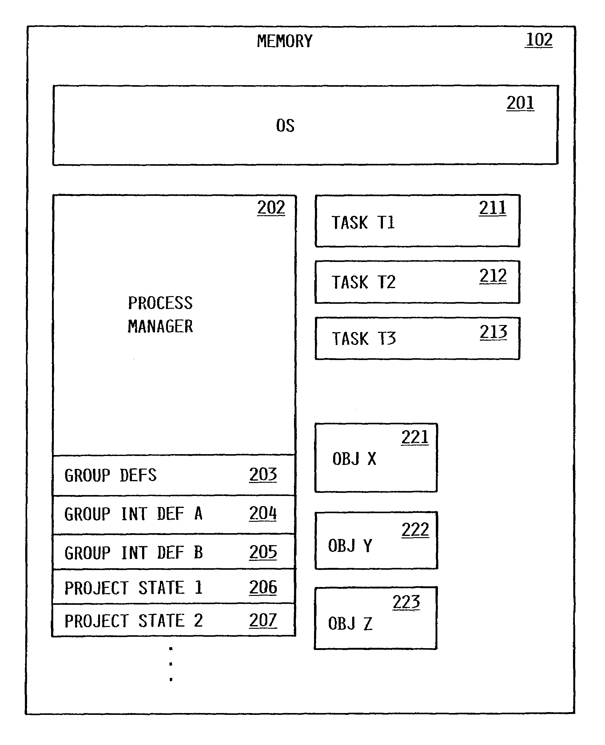
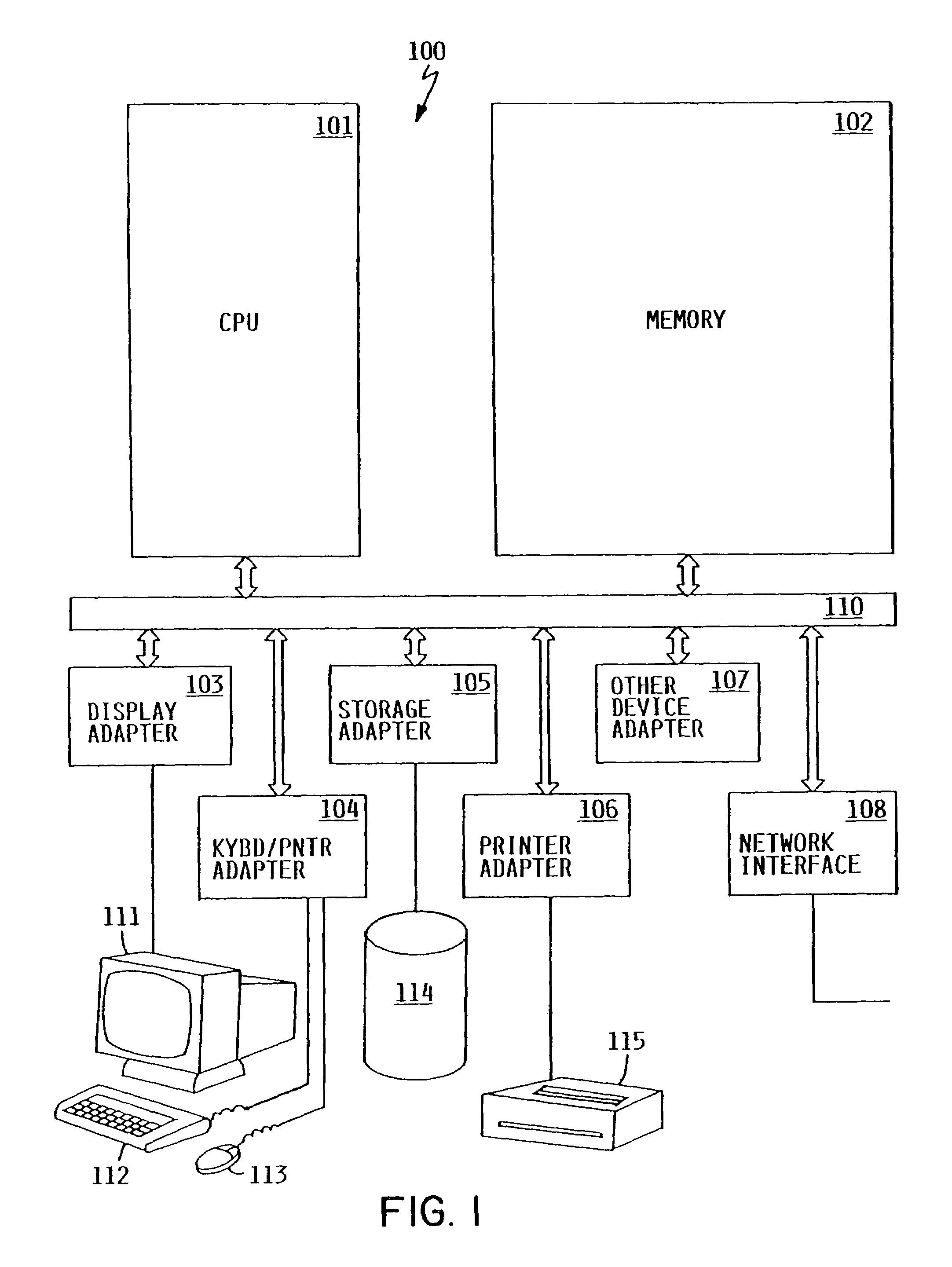
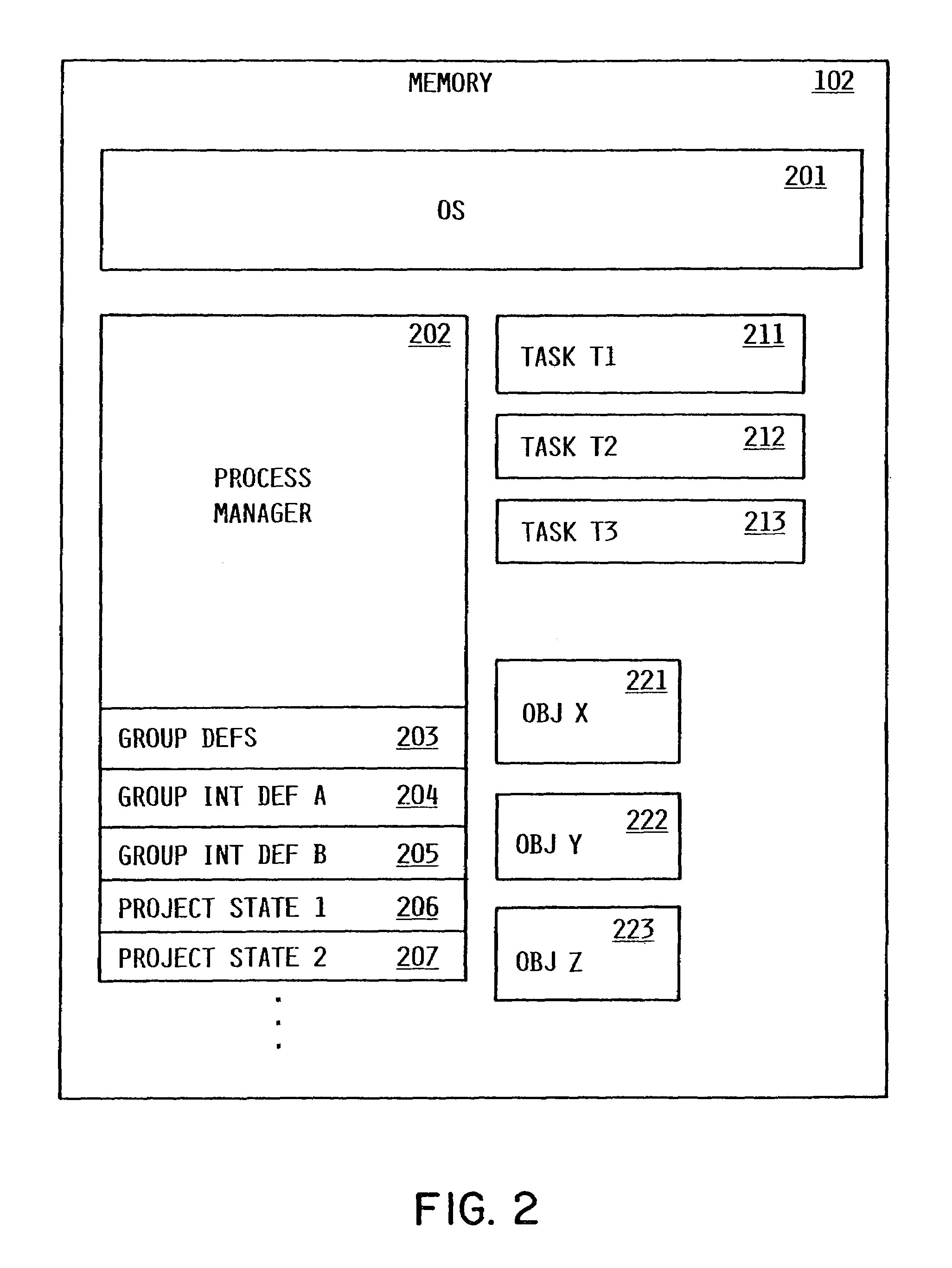
[0029]Referring to the Drawing, wherein like numbers denote like parts throughout the several views, FIG. 1 is a high-level block diagram of a typical client workstation computer system 100, from which process tasks are performed by a user, according to the preferred embodiment. Client workstation computer system 100 includes CPU 101, main memory 102, various device adapters and interfaces 103–108, and communications bus 110. CPU 101 is a general-purpose programmable processor, executing instructions stored in memory 102; while a single CPU is shown in FIG. 1, it should be understood that computer systems having multiple CPUs could be used. Memory 102 is a random-access semiconductor memory for storing data and programs; memory is shown conceptually as a single monolithic entity, it being understood that memory is often arranged in a hierarchy of caches and other memory devices. Communications bus 110 supports transfer of data, commands and other information between different device...


PUM


Abstract

A process manager supports the interactive definition of multiple user groups having access to process application software, and for each group, the interactive definition of a respective group interface which is unique to the group. Preferably, the group interface is a project tracking notepad which lists tasks applicable to the group, and functions as both a selection menu and a status indicator or reminder of actions to be performed or which have been performed. The project tracking notepad is an alternative user interface, which exists in addition to any other user interfaces available. Preferably, an administrator defines, for each group, the task selections applicable to the group, and the task description which will display on project tracking notepad. Thus it is possible to describe the same task with different descriptive words or phrases when the task selection is displayed in the notepads of different groups. Each task selection displayed in a project tracking notepad contains a respective status indicator, which is preferably a colored light. The process management function described herein provides diverse groups of users with easy-to-understand project menus which are specific to the group, do not include superfluous task selections, and use descriptive terminology meaningful to the group. Furthermore, such project menus are easily customizable and editable by a process administrator or similar user.

Description

FIELD OF THE INVENTION[0001]The present invention relates to digital data processing, and in particular, to computer methods and systems for management of projects involving multiple computer users.BACKGROUND OF THE INVENTION[0002]The latter half of the twentieth century has been witness to a phenomenon known as the information revolution. While the information revolution is a historical development broader in scope than any one event or machine, no single device has come to represent the information revolution more than the digital electronic computer. The development of computer systems has surely been a revolution. Each year, computer systems grow faster, store more data, and provide more applications to their users.[0003]Early computer systems were very expensive and difficult to use, capable of being programmed and manipulated by only a handful of highly-educated specialists. The cost of operating such computers was correspondingly high, and they were therefore used for only th...

Claims


Application Information

Patent Timeline
IPC IPC(8): G06F17/30
CPCG06Q10/103Y10S707/99943Y10S707/99945Y10S707/99942
Inventor MITCHELL, TODD ANTHONYTANABE, ANDREW T.
Owner IBM CORP
Learn More