Applicator device

a technology of a splicing device and a splicing plate, which is applied in the direction of carpet cleaners, packaging foodstuffs, packaged goods types, etc., to achieve the effect of facilitating rapid assembly of segments

Inactive Publication Date: 2007-07-12
DUSA PHARMA INC
View PDF31 Cites 24 Cited by
  • Summary
  • Abstract
  • Description
  • Claims
  • Application Information

AI Technical Summary

Benefits of technology

[0004] An applicator device of a present invention comprises a handle having a first end and a second end and a head portion rotatably attached to the first end of the handle. The head portion has an attachment means for releasably securing a pad engagement member mounted on one of its surfaces. The attachment means for releasably securing a pad engagement member can be a portion of loop bearing material that can be adhesively mounted to the head portion. The handle can be collapsible and can be made of a plurality of interlocking segments. The interlocking segments can be substantially configured as hollow tubes. An elastic connecting means can extend through the hollow interiors of the tubes to facilitate rapid assembly of the segments into an operable handle.
[0005] In another aspect the invention comprises a kit

Problems solved by technology

In addition, certain areas of the skin that need

Method used


Image

  • Applicator device
  • Applicator device
  • Applicator device

Examples


Embodiment Construction

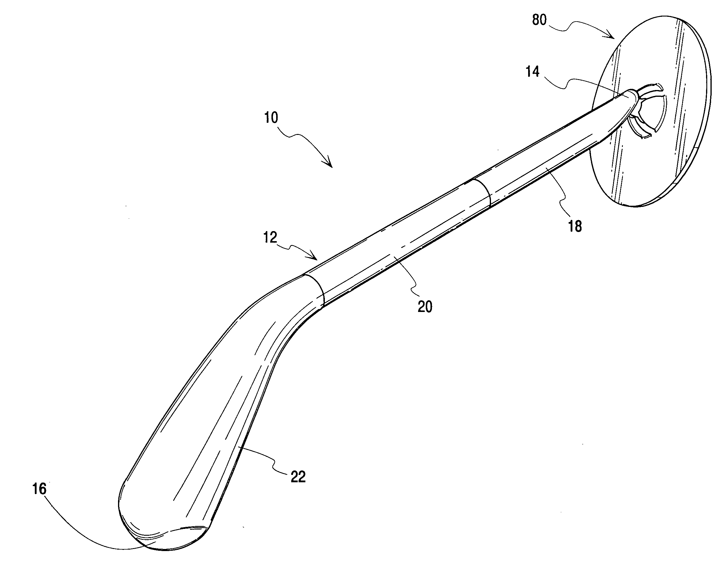
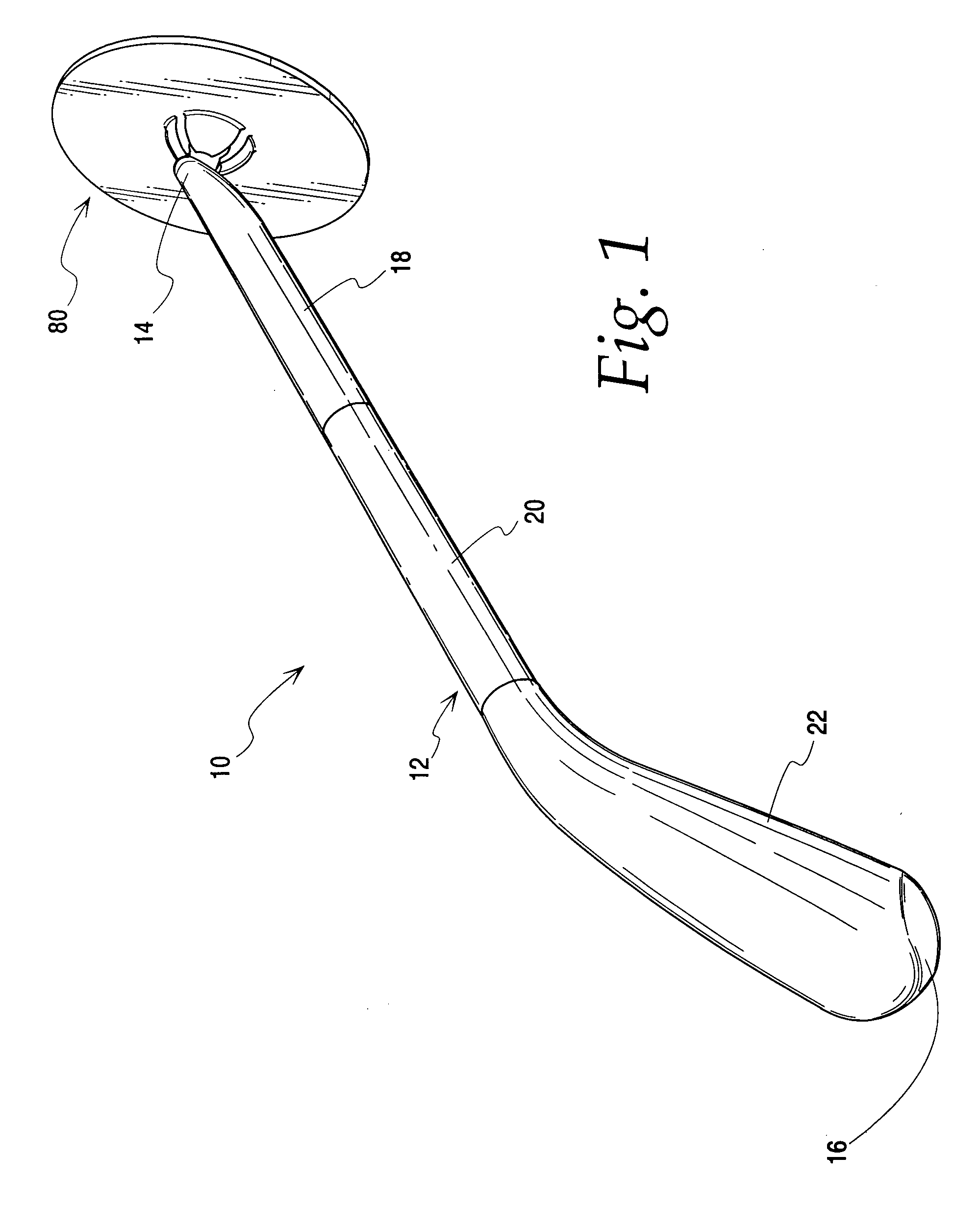
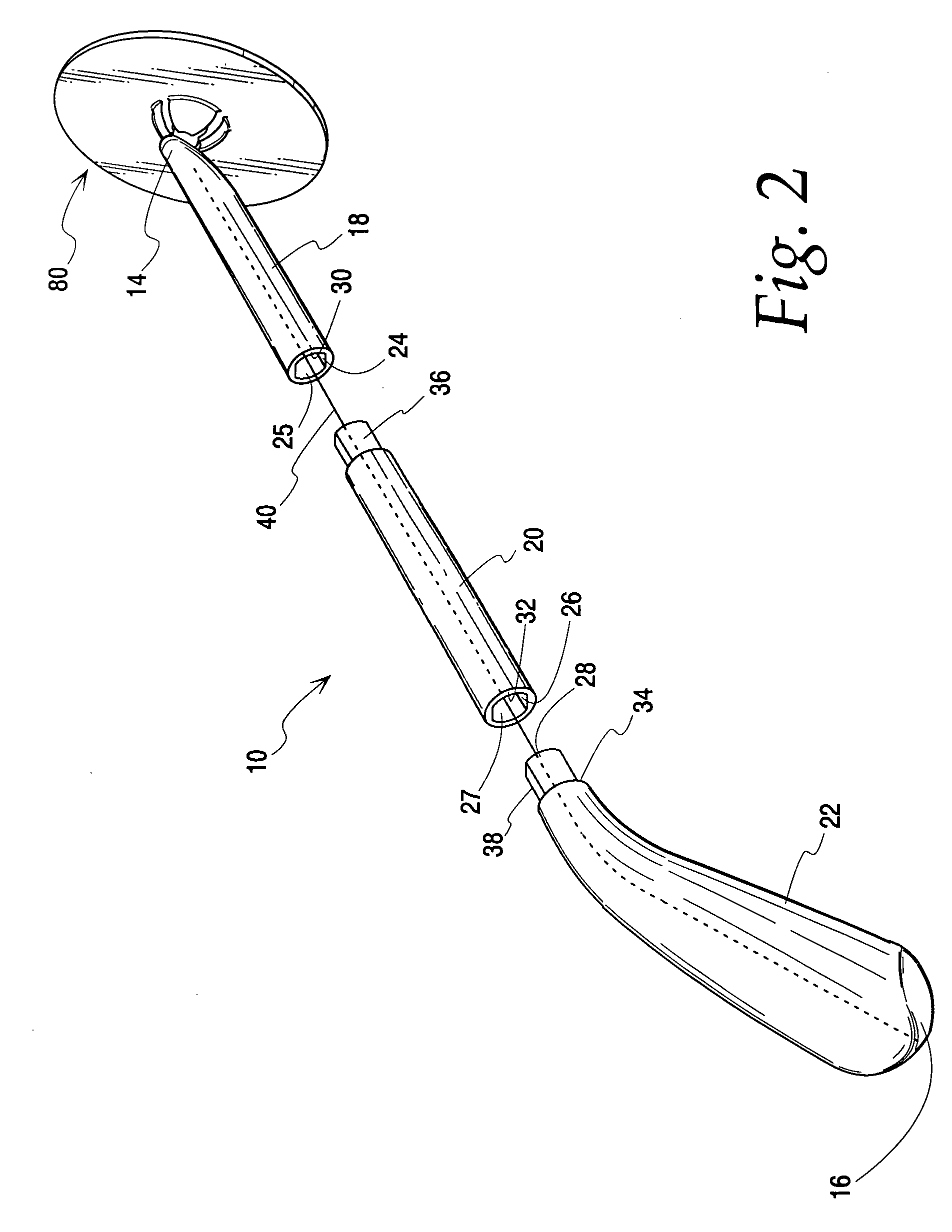
[0013] Referring to FIGS. 1 and 2, an applicator device 10 of the present invention comprises a handle 12 and a head portion 80. The handle 12 includes a first end 14 and a second end 16. The handle may comprise a plurality of interlocking segments. In the illustrated embodiment there are three such segments indicated at 18, 20 and 22. Each of these segments is substantially in the form of a hollow tube having interior regions 24, 26 and 28, respectively, and circumferential walls 30, 32 and 34 respectively. As illustrated in FIG. 2, extending from the circumferential wall 32 of segment 20 is a neck member 36 which fits into opening 25 of the hollow region 24 of segment 18. Similarly, extending from segment 22 is a neck member 38 which fits into opening 27 of the hollow region 26 of segment 20. As illustrated in FIG. 2, each neck member 36, 38 is of a non-circular cross-section, and the openings 25, 27, respectively, into which they fit are also of a complementary non-circular cross...


PUM


Abstract

An applicator device for applying a substance to an area of the body that is difficult to reach includes a collapsible handle and a head portion rotatably mounted on one end. The head portion includes an attachment means, which can comprise either a field of hooks or a field of loops. The attachment means receives a two-sided pad engagement member that preferably has fields of loops or hooks on one side to engage the respective hooks or loops of the attachment member, and a field of hooks on its opposite side. The hooks of the pad engagement member can securely retain a pad that carries the substance to be applied to the body.

Description

[0001] This invention relates to a device for applying a substance to a body. More particularly, this invention relates to a device for applying a substance to a portion of the body that is difficult to reach, such as the back. BACKGROUND OF THE INVENTION [0002] Many people apply substances to their skin to treat conditions of the skin and to promote general health and well-being of the skin. These substances are frequently in the form of lotions, creams, solutions or ointments. These substances may need to be applied to certain portions of the body that are difficult for an individual to reach, such as certain areas of the back. [0003] In addition, certain areas of the skin that need treatment may harbor bacteria or other pathogens. It is therefore possible that some of these pathogens could be transferred to an applicator device and then come into subsequent contact with the skin when the applicator device is directed to a different portion of the body. It would therefore be desir...

Claims


Application Information

Patent Timeline
IPC IPC(8): A47K7/02
CPCA45D34/04A45D2200/1081A45D2200/1018
Inventor BARGIEL, MICHAELNELSON, JOSHUA J.WALTERS, GLENNPOLLARD, FRANK
Owner DUSA PHARMA INC
Why Eureka
Try Eureka