
Foam wheel cladding process

a foam wheel and cladding technology, applied in the field of vehicle wheels, can solve the problems of high cost, inability to stamp or draw the wheel disc, and inability to use adhesives, etc., and achieve the effect of avoiding the possibility of complications, avoiding the use of adhesives, and avoiding the possibility of slipping

Inactive Publication Date: 2007-07-12
MCKECHNIE VEHICLE COMPONENTS USA
View PDF27 Cites 17 Cited by
  • Summary
  • Abstract
  • Description
  • Claims
  • Application Information

AI Technical Summary

Problems solved by technology

The decorative cover in Derleth is configured to have variations in contour in a direction transverse to the axis of the wheel which exceed the variations in the rim and / or disc contour of the wheel, which variations would be extremely difficult and expensive, if not impossible, to stamp or draw in the disc of the wheel.
The inclusion of turbine openings in wheels and wheel covers creates problems with the use of adhesives.
A disadvantage of the process of Chase et al. is that, since Chase et al. relies upon the latent heat of the wheel / overlay assemblies (from the heating station), it is necessary to include a check station in which the temperature of the wheel / overlay assemblies is monitored.
This manner of operation is susceptible to complications especially when problems occur at the filling station, causing delays in the transfer of the heating wheel / overlay assemblies.
In addition, since Chase et al. holds the wheel / overlay assemblies together at the filling station until the injected foamable adhesive has cured, bottle-necking of the overall process can occur at the filling station, especially when the latent heat is marginal and curing takes a longer time.

Method used


Image

  • Foam wheel cladding process
  • Foam wheel cladding process
  • Foam wheel cladding process

Examples


Embodiment Construction

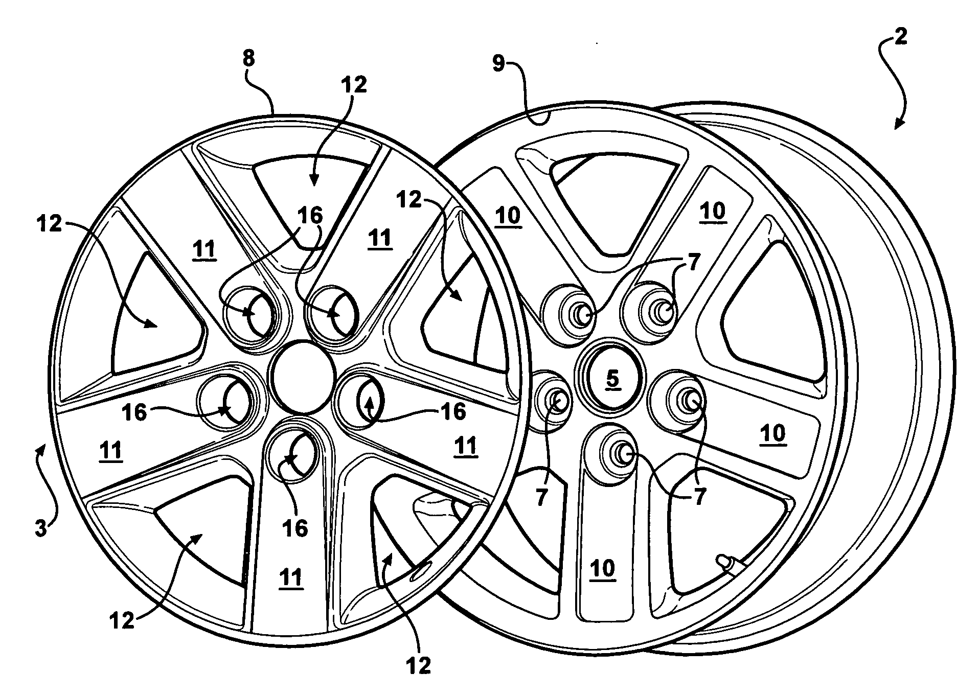
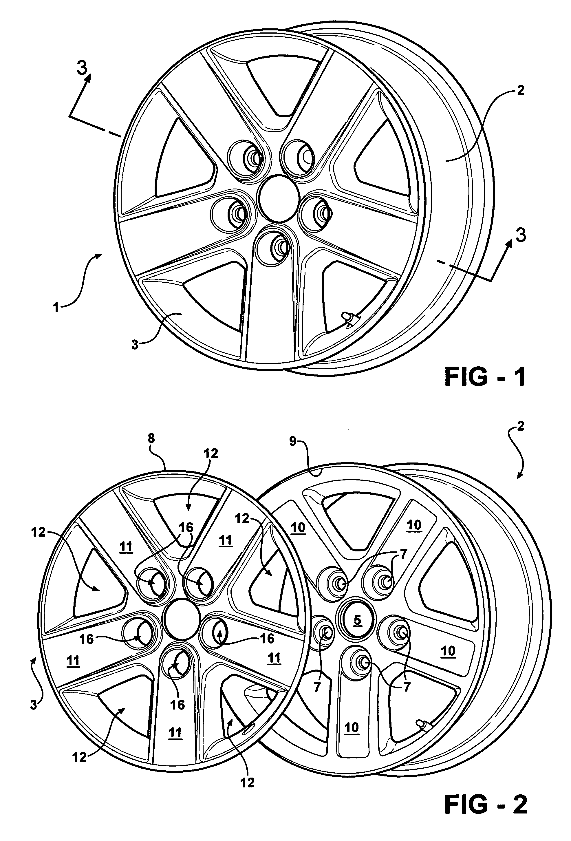
[0039] The present invention is directed to a method for adhesively securing decorative wheel covers to wheels using an injectable, foamable adhesive. The process can be used in conjunction with wheel covers that are made from various plastic materials or metals, including stainless steel. The underlying wheel can be made of aluminum, magnesium, steel, or other conventional material. The overall wheel assembly can have virtually any desired design configuration, including various spoke designs and / or various brake vent opening shapes and / or patterns.

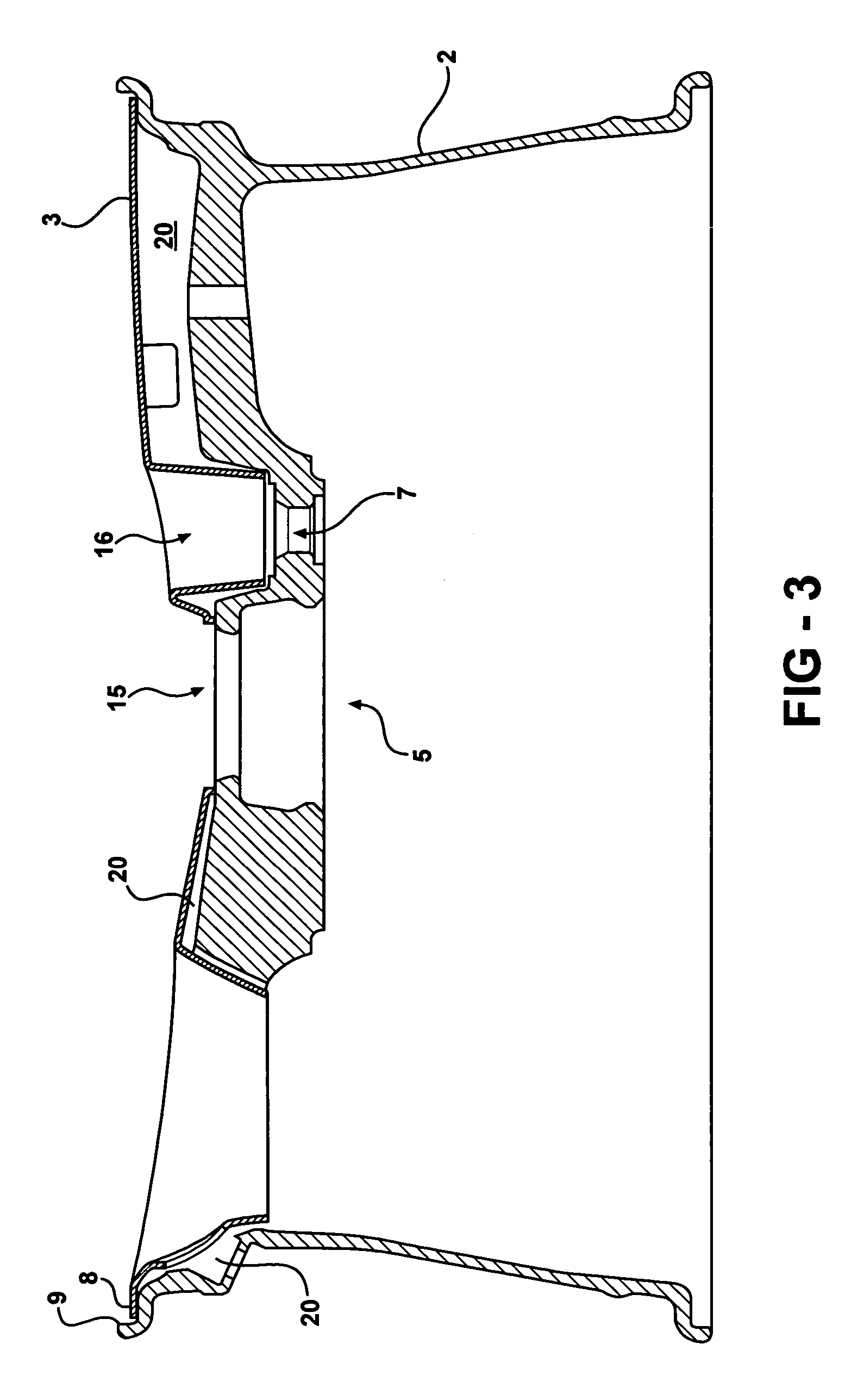
[0040] The process of the present invention involves positioning a wheel cover on a wheel and injecting a foamable adhesive in the cavity or space defined between the wheel cover and the wheel. The cavity or space defined between the wheel cover and the wheel has a configuration which is dependent upon the difference in the topographies or shapes of the inboard surface of the wheel cover and the outboard surface of the wheel. In some ar...


PUM

PropertyMeasurementUnit
temperatureaaaaaaaaaa

Abstract

A process for attaching a wheel cover to a wheel in which a wheel cover and wheel are placed together and a foamable adhesive is injected into the gap defined between the wheel cover and wheel. After the foamable adhesive is injected into the gap defined between the wheel cover and wheel at an injection station, the cover / wheel assembly is transported to a station in which the cover / wheel assembly is heated to a temperature that is sufficient to effect the forming, expansion and curing of the foamable adhesive. The cover / wheel assemblies are supported and transported on carriers that are provided with clamping mechanisms.

Description

TECHNICAL FIELD [0001] The present invention relates to vehicle wheels that have decorative wheel covers secured over the wheels for aesthetic purposes. More specifically, the present invention relates to methods for adhesively securing decorative wheel covers to wheels during fabrication of the resulting wheel assemblies. BACKGROUND ART [0002] Wheel assemblies that utilize wheel appliqués to decorate the external or outboard surfaces of plain steel wheels are well known and are far less expensive to produce than decorative wheels that have to be formed and finished. [0003] Wheel appliqués can be secured to wheels by various mechanical engaging structures and / or by adhesives. U.S. Pat. No. 5,664,845 to Maloney et al. discloses a vehicle wheel cover retention system in which the annular lip of the wheel cover is configured to spring outwardly into a groove provided in the inner surface of the wheel. U.S. Pat. No. 5,595,423 to Heck et al. discloses a vehicle wheel cover retention syst...

Claims


Application Information

Patent Timeline
Patent Type & Authority Applications(United States)
IPC IPC(8): B21D53/26
CPCB60B7/0053B60B7/02B60B7/06Y10T29/4954Y10T29/49885Y10T29/49542Y10T29/49492B60B31/06
Inventor MURRAY, SCOTT L.
Owner MCKECHNIE VEHICLE COMPONENTS USA
Learn More