Device for wrapping a bale of pasture or the like

a technology for wrapping bales and pastures, applied in the field of wrapping devices, can solve the problems of dragging nets or the like into the baling chamber, affecting the quality of pastures,

Inactive Publication Date: 2007-07-12
OFF MEC ING A FERABOLI
View PDF4 Cites 32 Cited by
  • Summary
  • Abstract
  • Description
  • Claims
  • Application Information

AI Technical Summary

Benefits of technology

[0019] b) the total integrity of the wrapping means (that is of a net or the like), since that wrapping means is no more forced to pass through two metal sheet parts.

Problems solved by technology

A first disadvantage of employing this system is that the net or the like, which is dragged into the baling chamber, could possibly be damaged during its passage between the sheet metal parts, because it is subjected to sliding friction with the material of the sheet metal parts.
Unlike the binding system that makes use of a wire, the system which utilises a wrapping means (such as a net or a plastic film) that extends through the whole width of the baling chamber also has the problem of maintaining an outstretched condition of the net or plastic sheet, when the latter are unwound from the storage coil.
However, this relative movement could damage the net, as has already been highlighted.

Method used


Image

  • Device for wrapping a bale of pasture or the like
  • Device for wrapping a bale of pasture or the like
  • Device for wrapping a bale of pasture or the like

Examples


first embodiment

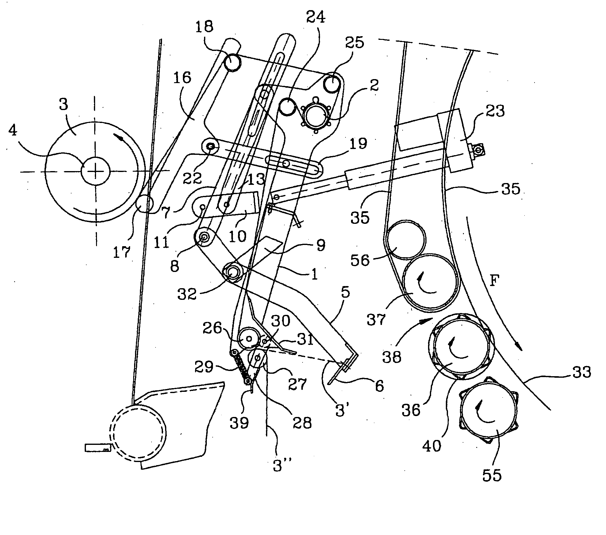
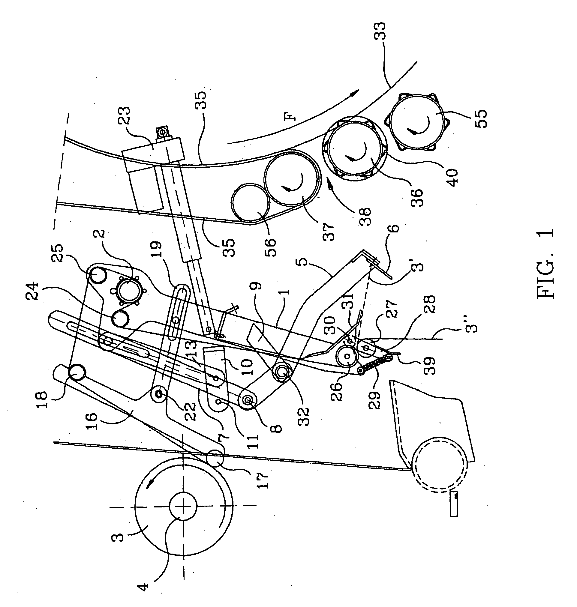
[0032] Referring first to FIG. 1, this figure shows the wrapping device of the invention in the rest position. This figure is very schematic, and it only shows those parts which are necessary to understand the invention, whereas the remaining parts (which are standard in round balers) will be omitted altogether for simplicity since the skilled person is already aware of their existence. The wrapping device first includes a dispensing device 1, taking the form of a rocker lever, and including two arms that are pivotly mounted around the axis 2. In reality, the two arms of the rocker lever 1 may swivel around the outer side of two respective rings which are fixed to the respective opposite inner side walls of the round baler. On the inner part of these rings there are provided bearings for a transversal shaft 2, which extends between the rings, said transversal shaft being idly mounted in order to permit the advancement of the net.

[0033] Moreover, the wrapping device comprises a “res...

second embodiment

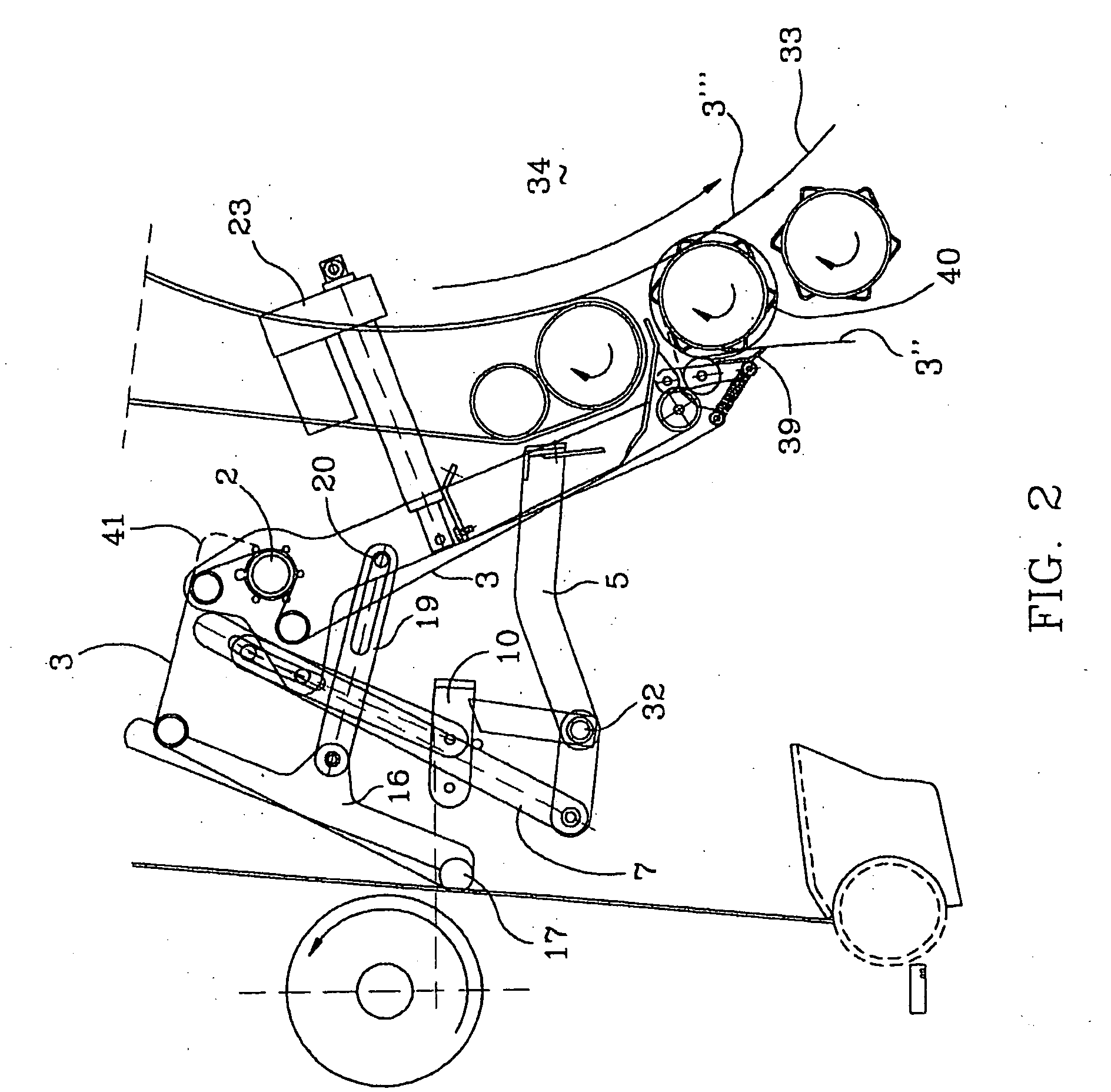
[0055] With reference to FIGS. 4, 5, 6 and 7, we will now describe the present invention.

[0056] This second embodiment differs from the first only in some features, so that the same reference numbers will be maintained as much as possible, except (obviously) for components that have no identical counterpart.

[0057] Nor will it be necessary to repeat the preceding description for identical parts that are already contained in the first embodiment.

[0058] In this second embodiment, the lower part of the rocker lever 1 differs from the first embodiment in that besides the two rollers 26, 27—in the present case denoted by 26′, 27′—there is provided a third roller 42. Moreover, the roller 42 is idly mounted on a second lever 43 which is pivoted on the respective arm of the rocker lever 1, while a spring 44 (one for each arm of 1) connects the free end of the lever 43 to the free end of the lever 28′. The net 3 extends along a zigzag path between the three idle rollers 26′, 27′, 42. Howeve...


PUM

PropertyMeasurementUnit
angleaaaaaaaaaa
circumferenceaaaaaaaaaa
resistanceaaaaaaaaaa

Abstract

A wrapping device for a round baler including a rocker lever ( 1 ), at whose lower end there is mounted a group of gripping rollers ( 26, 27 ) for gripping a free end ( 3 '') of a wrapping element ( 3 ) taken from a storage element ( 4 ). One of the rollers ( 26, 27 ) preferably carries spiral ribs and could be motor-driven.

Description

TECHNICAL FIELD [0001] The present invention relates to a wrapping device used for wrapping a bale of hay or the like, and which is mounted on a round baler. BACKGROUND ART [0002] Generally at the end of the bale formation cycle, when the bale has reached a desired diameter, it is necessary that the round baler perform the wrapping of the bale of pasture or the like. [0003] This wrapping or binding operation, as is well known to those skilled in the art and those who use round balers, is performed by means of a wire or by means of a sheet-like material (e.g. a net), while the bale is still inside the round baler. After the wrapping or binding, the bale is discharged on the ground from the tailgate. In modern round balers the whole process is essentially automatic, and the operator only needs to set the final (desired) bale diameter, possibly in combination with other parameters like the density of the bale etc. [0004] As regards the binding systems which make use of a wire, they hav...

Claims


Application Information

Patent Timeline
Patent Type & Authority Applications(United States)
IPC IPC(8): B65B27/12B65B11/04A01F15/07B65B11/00
CPCA01F2015/0725A01F15/0715
Inventor FERABOLI, ANTONIOCAGLIERI, VANNI
Owner OFF MEC ING A FERABOLI
Why Eureka
Try Eureka