Interference-seal plunger for an artificial lift system

a technology of interfacial sealing and plunger, which is applied in the direction of sealing/packing, fluid removal, borehole/well accessories, etc., to achieve the effect of enhancing the movement of the body over the drag

Inactive Publication Date: 2007-07-12
CASEY DANNY M
View PDF34 Cites 28 Cited by
  • Summary
  • Abstract
  • Description
  • Claims
  • Application Information

AI Technical Summary

Benefits of technology

[0010] In another embodiment the plunger may include a solid body adapted to travel within a production string positioned in a wellbore. At least one sealing ring is connected about the body. The at least one sealing ring having an inner surface, an outer surface, a width and a thickness. The width is sufficient such that when the body is disposed in the production string, the outer surface contacts and substantially forms a seal between the body and an inner wall of the production string. The at least one sealing ring has a width to thickness ratio within a range from about 0.02 to 0.2 wherein when the body is disposed within the production string, the sealing ring assumes a shape such that the sealing ring enhances movement of the body over the drag from the sealing contact.

Problems solved by technology

The sealing rings may have an outside diameter greater than the inner diameter of the production tubing within which the body is adapted to travel such that when the body is disposed within the production string, an interference fit causes the sealing rings to roll-form into a constricted shape and diameter that exerts the sealing contact with the production string.

Method used


Image

  • Interference-seal plunger for an artificial lift system
  • Interference-seal plunger for an artificial lift system
  • Interference-seal plunger for an artificial lift system

Examples


Embodiment Construction

[0018] Refer now to the drawings wherein depicted elements are not necessarily shown to scale and wherein like or similar elements are designated by the same reference numeral through the several views.

[0019] As used herein, the terms “up” and “down”; “upper” and “lower”; and other like terms indicating relative positions to a given point or element are utilized to more clearly describe some elements of the embodiments of the invention. Commonly, these terms relate to a reference point as the surface from which drilling operations are initiated as being the top point and the total depth of the well being the lowest point.

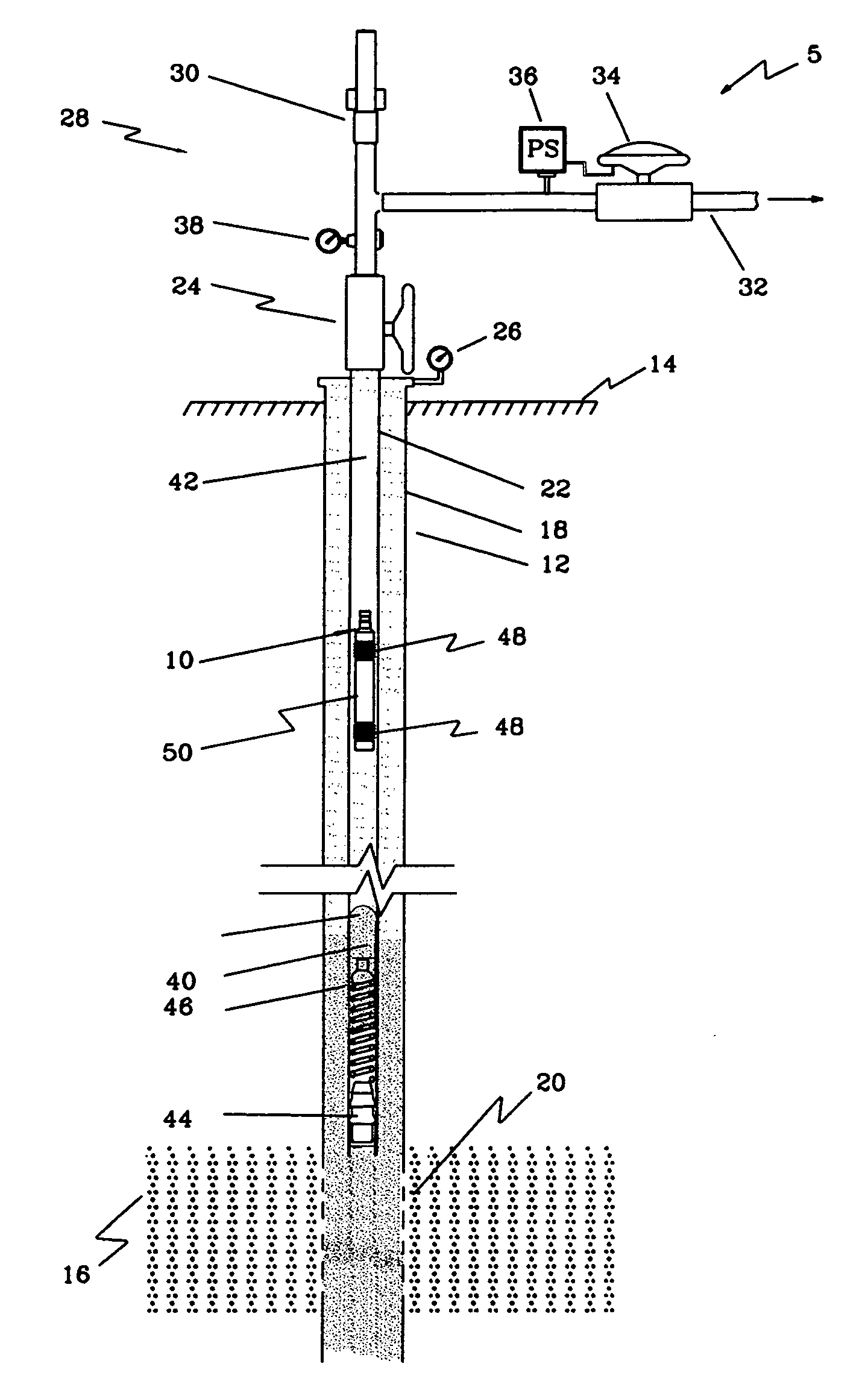
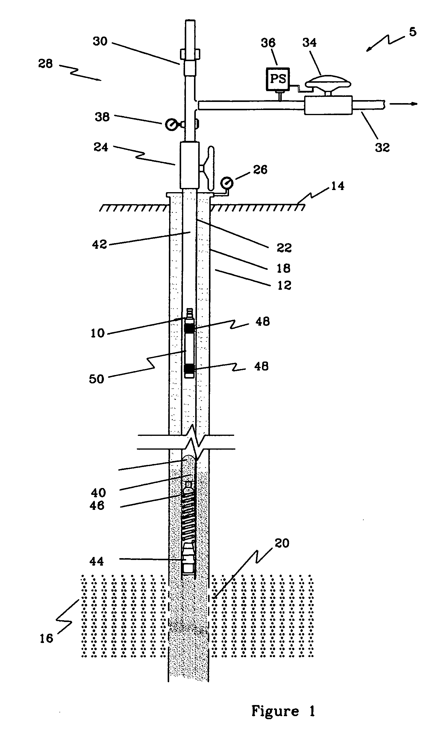
[0020]FIG. 1 is a schematic drawing of an embodiment of a plunger lift system 5 utilizing an interference-seal plunger of the present invention, generally denoted by the numeral 10. The well includes a wellbore 12 extending from the surface 14 of the earth to a producing formation 16. Wellbore 12 may be lined with a casing 18 including perforations 20 proximate pr...


PUM


Abstract

A plunger for an artificial lift system and embodiment of the plunger includes a solid body adapted to travel within a production string positioned in a wellbore. At least one sealing ring connected about the body. The at least one sealing ring having an inner surface, an outer surface, a width and a thickness. The width is sufficient such that when the body is disposed in the production string the outer surface contacts and substantially forms a seal between the body and an inner wall of the production string. The at least one sealing ring having an outside diameter greater than the inner diameter of the production tubing within which the body is adapted to travel such that when the body is disposed within the production string an interference fit causes the sealing rings to roll-form into a constricted shape and diameter that exerts the sealing contact with the production string.

Description

FIELD OF THE INVENTION [0001] The present invention relates in general to producing fluids from a well and more specifically to an interference-seal plunger for a plunger lift system. BACKGROUND [0002] In the life of most wells the reservoir pressure decreases over time resulting in the failure of the well to produce fluids utilizing the formation pressure solely. As the formation pressure decreases, the well tends to fill up with liquids, such as oil and water, which inhibits the flow of gas into the wellbore and may prevent the production of liquids. It is common to remove this accumulation of liquid by artificial lift systems such as plunger lift, gas lift, pump lifting and surfactant lift wherein the liquid column is blown out of the well utilizing the reaction between surfactants and the liquid. [0003] One method of producing fluids from a declining well having gas production is by utilizing a plunger lift system. A well is shut-in allowing a plunger to fall through the fluid c...

Claims


Application Information

Patent Timeline
Patent Type & Authority Applications(United States)
IPC IPC(8): E21B43/00
CPCE21B43/121
Inventor CASEY, DANNY M.
Owner CASEY DANNY M
Why Eureka
Try Eureka