Disk brake with a parking brake function

a technology of parking brake and disk brake, which is applied in the direction of electrodynamic brake system, mechanical apparatus, transportation and packaging, etc., can solve the problems of limited movement of the pressing member in the direction of the piston movement, and achieve the effect of large piston thrust, large piston thrust, and correspondingly reduced piston thrus

Inactive Publication Date: 2007-07-12
HITACHI LTD
View PDF10 Cites 39 Cited by
  • Summary
  • Abstract
  • Description
  • Claims
  • Application Information

AI Technical Summary

Benefits of technology

[0012] Since the space between the piston and the pressing member is sealed by the sealing member, the disk brake with the parking brake mechanism can utilize a pressure receiving area equal to a cross section of the entire portion of the piston when the pressing member is driven by the electric motor to slide and then to move forward with the piston during a parking brake operation. In this way, a large piston thrust can be obtained. On the other hand, during a service brake operation, in which the electric motor is in a rotational position for parking brake release, movement of the pressing member in a direction of movement of the piston is limited. Therefore, the piston alone moves forward. In this state, the pressure receiving area is equa...

Problems solved by technology

On the other hand, during a service brake operation, in which the electric motor is in a rotational positio...

Method used


Image

  • Disk brake with a parking brake function
  • Disk brake with a parking brake function
  • Disk brake with a parking brake function

Examples


Embodiment Construction

[0023] Below, the best mode for carrying out the present invention will be described with reference to the accompanying figures.

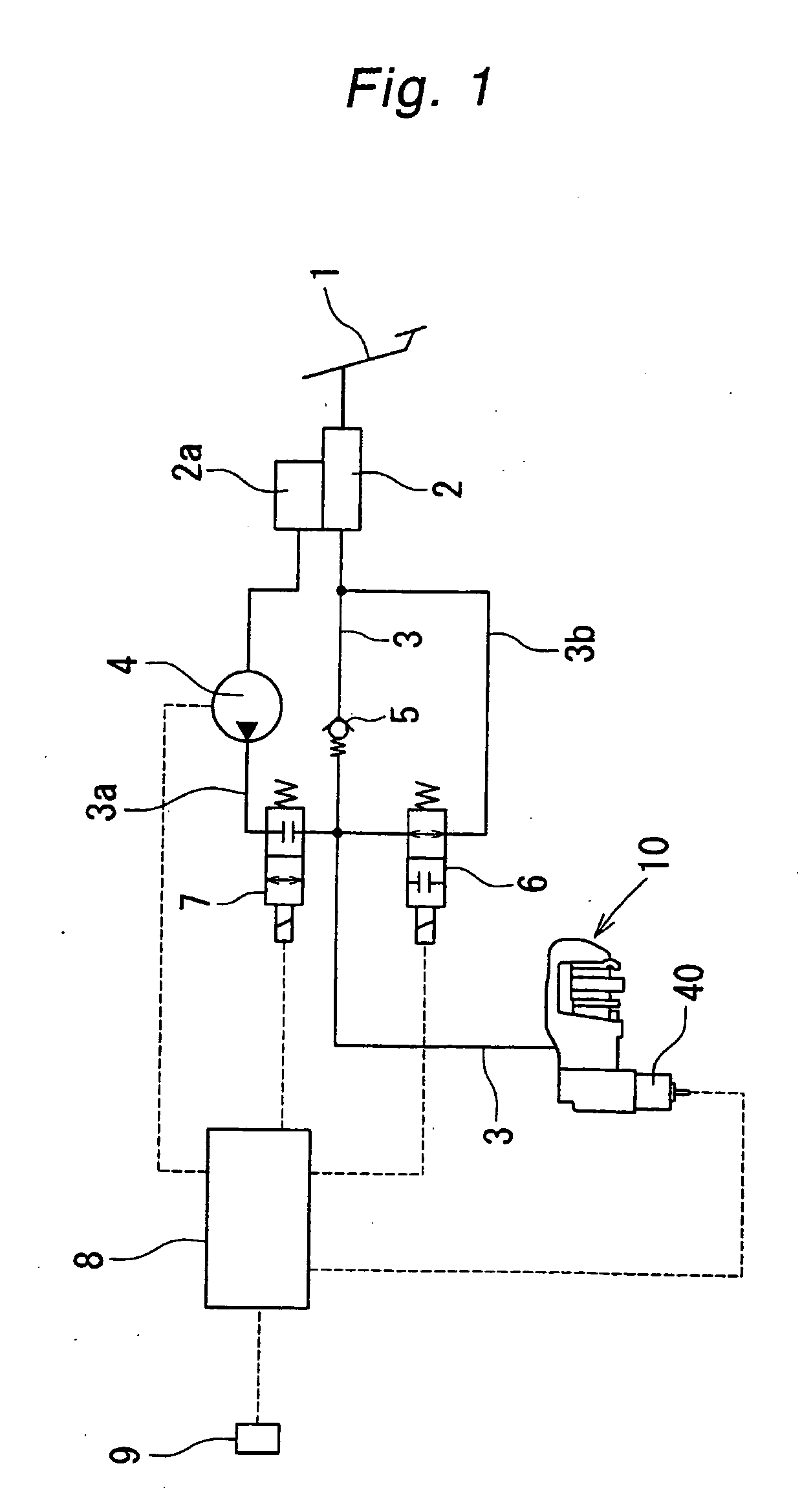
[0024]FIG. 1 shows a brake system including a disk brake with an electric parking brake mechanism according to the present invention. The disk brake with the electric parking brake mechanism, which is denoted by reference numeral 10 in FIG. 1, is connected via a brake fluid passage 3 to a master cylinder 2 adapted to generate a hydraulic pressure according to operation of a brake pedal 1, and is also connected to a pump 4 via a branch passage 3a that is branched off from the brake fluid passage 3 and connected to a reservoir 2a. The brake fluid passage 3 is provided at an intermediate portion thereof with a check valve 5 for preventing a counter flow toward the master cylinder 2. A branch passage 3b, which bypasses the check valve 5, is provided with an electromagnetic switching valve 6 that is normally open, while the branch passage 3a is provided on a di...


PUM


Abstract

A disk brake with a parking brake mechanism capable of exerting a large piston thrust required for operating a parking brake, without adversely affecting operation of a service brake. A parking brake mechanism 32, which is driven by an electric motor provided outside a housing 30, is incorporated in a caliper 14 in which a piston 26 is slidably disposed in a cylinder 24. The parking brake mechanism 32 is slidably fitted via a seal member 36 into the piston 26 and provided with a nut member 37 that is prevented from rotating relative to the piston 26 by engagement of a pin 48 and a pin hole 49; and a shaft 35 that is screwed into the nut member 37. During a service brake operation, the piston 26 alone is moved by a hydraulic pressure under a small piston thrust. During a parking brake operation, the piston 26 and the nut member 37 are moved together by applying a hydraulic pressure and operating the electric motor at the same time, to exert a large piston thrust, by using a large pressure receiving area of the piston 26 and the nut member 37 combined.

Description

BACKGROUND OF THE INVENTION [0001] 1. Technical Field [0002] The present invention relates to an automotive disk brake, and in particular, to a disk brake with an electric parking brake having an electric parking brake function. [0003] 2. Prior Art [0004] Generally, an automotive disk brake comprises: a pair of pads disposed on opposite sides of a disk; and a caliper in which a piston is slidably provided in a cylinder having a closed end, such that a hydraulic pressure, when introduced into the cylinder, thrusts the piston to cause the pair of pads to press against the disk, thereby exerting a braking force. Recently, however, disk brakes with an electric parking brake, that is, disk brakes further equipped with an electric parking brake function, have come into use. An example of a conventional disk brake having an electric parking brake is disclosed in Domestic Announcement (KOHYO) No. HEI 05-506196 of PCT application. In this example, an electric motor, which is provided outside...

Claims


Application Information

Patent Timeline
IPC IPC(8): B60L7/00
CPCF16D65/18F16D2121/02F16D2125/52F16D2123/00F16D2125/40F16D2121/24
Inventor OHTANI, YUKIOKARASUDANI, YASUOOBATA, TAKUYA
Owner HITACHI LTD
Why Eureka
Try Eureka