Backlight module control circuit of multi-lamp display device

a control circuit and multi-lamp technology, applied in the direction of electrical devices, light sources, instruments, etc., to achieve the effect of enhancing the driving electric circuit and reducing the display quality of images

Inactive Publication Date: 2007-07-12
CHUNTEX ELECTRONICS
View PDF5 Cites 4 Cited by
  • Summary
  • Abstract
  • Description
  • Claims
  • Application Information

AI Technical Summary

Benefits of technology

[0007] The fault detection unit can detect whether any one of the lamps is out of order and then output a signal to the control unit, so as to make the control unit shut down the driving circuit of the failure lamp and continue to maintain an operation of other normal lamps. In this way, high voltage of the driving circuits can avoid damaging the display device by shutting down the high voltage of the driving circuit of the failure lamp. Moreover, the whole brightness of the display device still can keep normal without decreasing the display quality of the images by the control unit to enhance the driving electric circuit of the other normal lamps.

Problems solved by technology

However, a main drawback of the conventional control circuit is that when any one of the lamp is out of order, all of the other lamps are closed, so as to stop the display device.

Method used


Image

  • Backlight module control circuit of multi-lamp display device
  • Backlight module control circuit of multi-lamp display device
  • Backlight module control circuit of multi-lamp display device

Examples


first embodiment

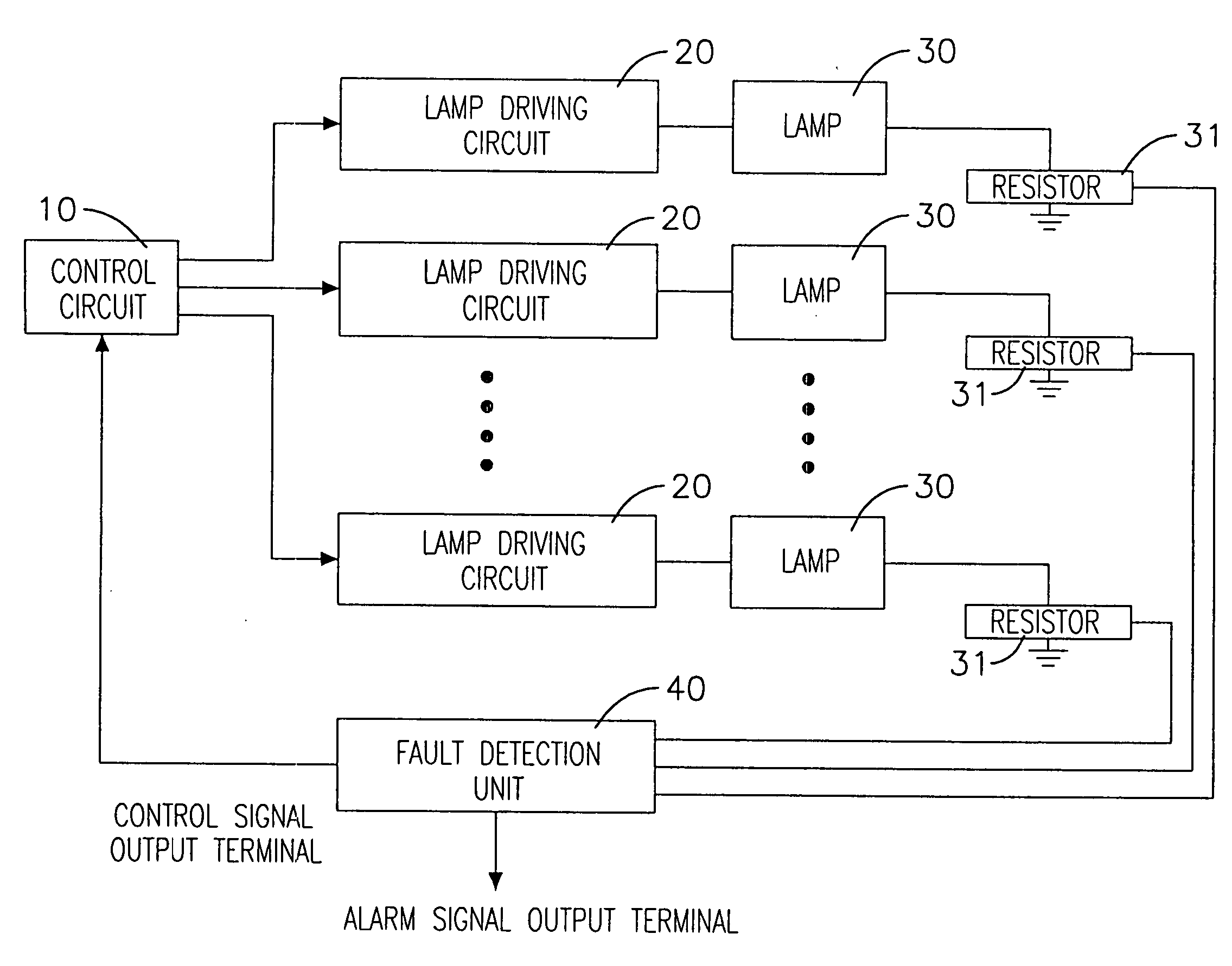
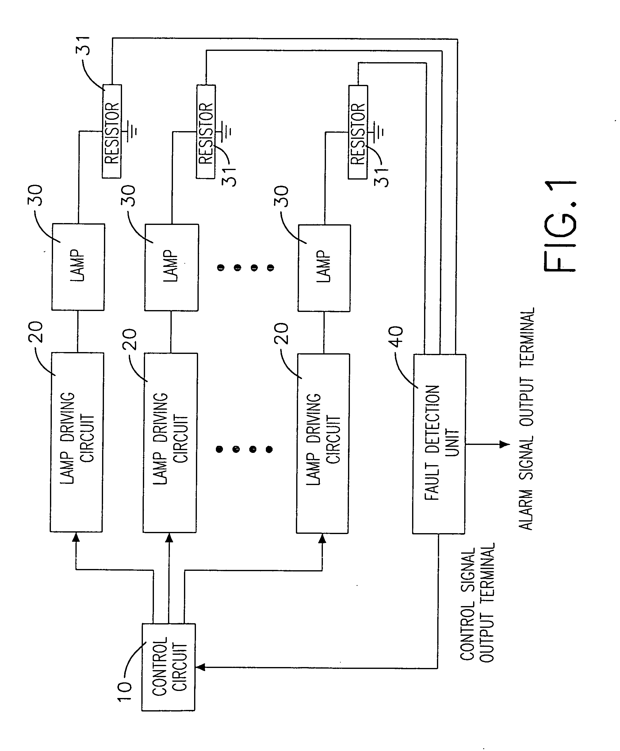
[0012] With reference to FIG. 1, a backlight module control circuit of a multi-lamp display device of the present invention includes a control unit 10, multiple lamp driving circuits 20 and a fault detection unit 40. The control unit 10 includes multiple signal output terminals. The control unit 10 can be made up by a microprocessor or a control circuit having active or passive electronic components.

[0013] Further, an input terminal of each lamp driving circuits 20 is coupled to a signal output terminal of the control unit 10. An output terminal of each lamp driving circuits 20 is coupled to a terminal of a lamp 30. The other terminal of the lamp 30 is coupled to the ground through a resistor 31. Each lamp driving circuits 20 includes an individual PWM controller to control on / off cycles of the corresponding lamps 30.

[0014] The fault detection unit 40 has multiple signal detection input terminals. The signal detection input terminals are respectively coupled to the lamp driving cir...

second embodiment

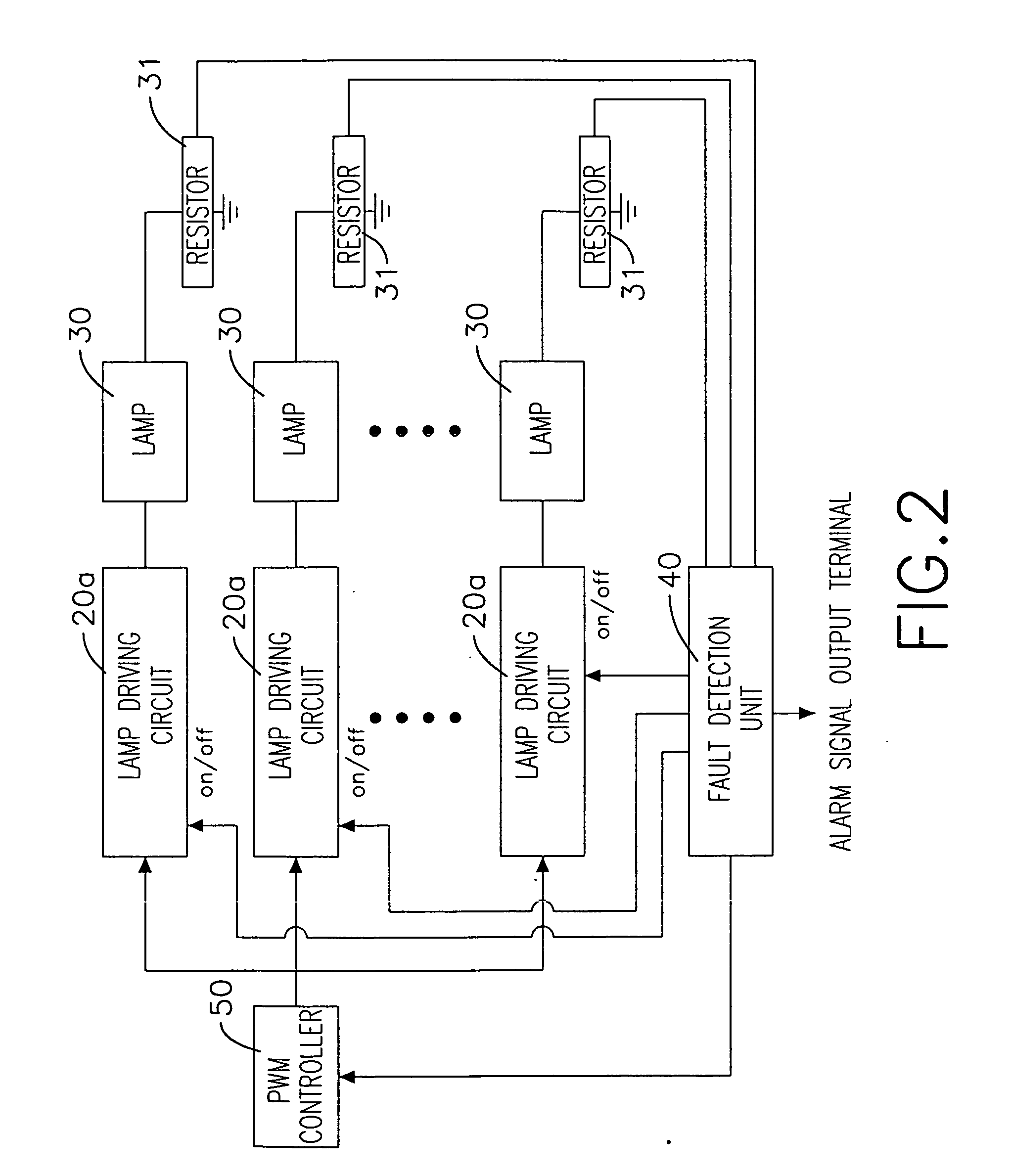
[0018] With reference to FIG. 2, a backlight module control circuit of a multi-lamp display device of the present invention includes a PWM controller 50, multiple lamp driving circuits 20a and a fault detection unit 40. The PWM controller 50 includes a signal output terminal. An input terminal of each lamp driving circuits 20a is coupled to the signal output terminal of the PWM controller 50. An output terminal of each lamp driving circuits 20a is coupled to a terminal of a lamp 30. The other terminal of the lamp 30 is coupled to the ground through a resistor 31.

[0019] The fault detection unit 40 includes multiple signal detection input terminals. The signal detection input terminals are respectively feedback-connected to the corresponding resistors 31 to detect whether any abnormal lamp 30 exists. The fault detection unit 40 further includes an alarm signal output terminal and a plurality of control signal output terminals. The control signal output terminals are feedback-connected...


PUM


Abstract

A backlight module control circuit of a multi-lamp display device includes a control unit, multiple lamp driving circuits and a fault detection unit. The control unit includes multiple signal output terminals. Input terminals of the lamp driving circuits are respectively coupled to a signal output terminal of the control unit and output terminals of the lamp driving circuits are respectively coupled to a terminal of a lamp. A fault detection unit includes multiple signal detection input terminals, which are respectively coupled to multiple lamp driving circuits and lamps. The fault detection unit can detect whether any one of the lamps is out of order and then output a signal to the control unit, so as to make the control unit shut down the driving circuit of the failure lamp and continue to maintain an operation of other normal lamps.

Description

BACKGROUND OF THE INVENTION [0001] 1. Field of the Invention [0002] The invention relates in general to a backlight module control circuit, and more particularly to a backlight module control circuit for a multi-lamp display device. [0003] 2. Description of the Related Art [0004] A flat display panel such as a plasma display panel or a liquid crystal display (LCD) becomes more and more popular nowadays. Although with the advances of processing technique, the size of the flat display panel is enlarged to satisfy the consumers. In terms of operation principle, a basic operation principle of the plasma display panel makes use of voltage to control gas molecules, so as to activate fluorescent material to produce chemical reaction to present various colors. Moreover, the light source of the LCD is provided by a backlight module configured inside the display. The backlight module includes a light emitting device, which is commonly made up by lamps. The number of the lamps varies in accord...

Claims


Application Information

Patent Timeline
IPC IPC(8): H05B41/36
CPCH05B41/2858H05B41/245
Inventor CHEN, SY-SHANGLENG, ALEXLEE, ALLENLIANG, HSIEN-MIN YEH
Owner CHUNTEX ELECTRONICS
Why Eureka
Try Eureka