
Multifunction device, control device, multifunction device control system, method of controlling multifunction device, program, and storage medium

a multi-functional device and control device technology, applied in the direction of digital output to print units, instruments, computing, etc., can solve the problems of deteriorating efficiency in the development of a new application by which the control device controls the multi-functional device, and achieve the effect of easy developmen

Active Publication Date: 2007-07-12
SHARP KK
View PDF3 Cites 56 Cited by
  • Summary
  • Abstract
  • Description
  • Claims
  • Application Information

AI Technical Summary

Benefits of technology

[0009] The present invention was done to solve the above-identified problem. The objective of the present invention is to provide a multifunction device, a control device, a multifunction device control system, a controlling method of the multifunction device, a program, and a storage medium, which allow new control on the multifunction device by a control device to be easily developed.
[0017] Therefore, in case where the multifunction device is controlled by an external control device, the control device outputs, to the multifunction device, a first control command independent of the types of the multifunction devices or a control instruction based on which such a first control command is generated. As a result, when new control is performed on a multifunction device by a control device, the control device is developed so as to generate a first control command shared between multifunction devices or a control instruction based on which such a first control command is generated. The control device is therefore easily developed.

Problems solved by technology

As a result, the efficiency in the development of a new application by which the control device controls the multifunction device is deteriorated.
As a result, in case where a control device controls the multifunction device in accordance with a new application, corresponding menu items, data of the input screen, and a program for displaying the data must be provided in the multifunction device, which is very troublesome.

Method used


Image

  • Multifunction device, control device, multifunction device control system, method of controlling multifunction device, program, and storage medium
  • Multifunction device, control device, multifunction device control system, method of controlling multifunction device, program, and storage medium
  • Multifunction device, control device, multifunction device control system, method of controlling multifunction device, program, and storage medium

Examples


example 1

CONCRETE EXAMPLE 1 IN CASE OF OPERATION IN COOPERATION WITH EXTERNAL APPLICATION: DOCUMENT MANAGEMENT APPLICATION

[0146] The following will describe a concrete example 1 where URL registration information is registered on the multifunction device 1 in the manner as above, and the multifunction device 1 operates in cooperation with an external application, with reference to the URL registration information.

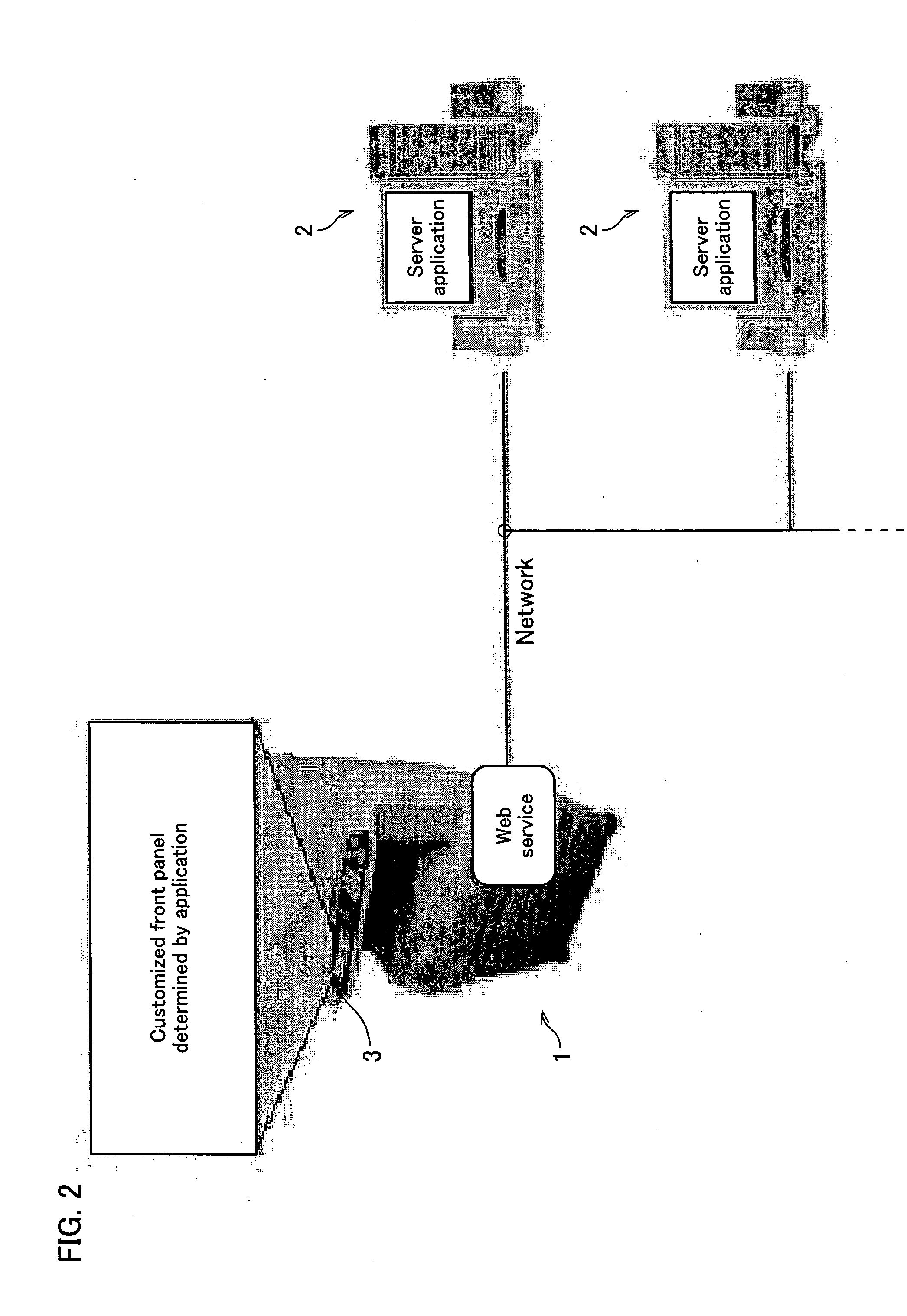
[0147] The present example illustrates a case where image data scanned by the multifunction device 1 is stored by a document management application in a control device 2. In this case, stored in the UI service layer 16 of the multifunction device 1 is URL registration information in which control identification information “Document Management” is associated with a URL of operation screen data indicating an operation screen for the cooperation with a document management application.

[0148]FIG. 14 illustrates the flow of a process in the present example.

[0149] First, the UI manager...

example 2

VARIANT EXAMPLE OF CONCRETE EXAMPLE 2

[0192] In the above-described concrete example 2, the UI service layer 16 of the multifunction device 1 obtains data of login data input screen from the control device 2, causes the operation panel 6 to display the login data input screen, and obtains login data from the input section 5. The login data, however, may be supplied from an external personal computer 4, instead of from the input section 5. The present variant example illustrates a case where the login data is obtained from an external personal computer 4. In the present variant example, the external personal computer is a print job generation device which outputs a print job to the multifunction device 1 and forms an image corresponding to the print data.

[0193]FIG. 22 shows the flow of a process in the present variant example.

[0194] First, the personal computer generates a print job and supplies the generated print job to the multifunction device 1 (S71). On this occasion, the perso...

example 3

CONCRETE EXAMPLE 3 IN CASE OF OPERATION IN COOPERATION WITH EXTERNAL APPLICATION: CONTROL USING AUTOMATIC TRANSLATION PROCESS

[0200] In the present embodiment, a background process can be carried out in the control device 2 while the operation screen of the multifunction device 1 is being changed. This makes it possible to improve the processing speed of the control device 2. The present concrete example is suitable for explaining this advantage.

[0201] In the present concrete example 3, the multifunction device 1 cooperates with an OCR application and a translation application in the application section 25 of the control device 2. That is to say, the OCR application extracts text data from image data scanned by the multifunction device 1, and the translation application translates the text data into another language. The translated document is then printed by the multifunction device 1.

[0202] In the present concrete example 3, the control device 2 obtains scanned image data from th...


PUM


Abstract

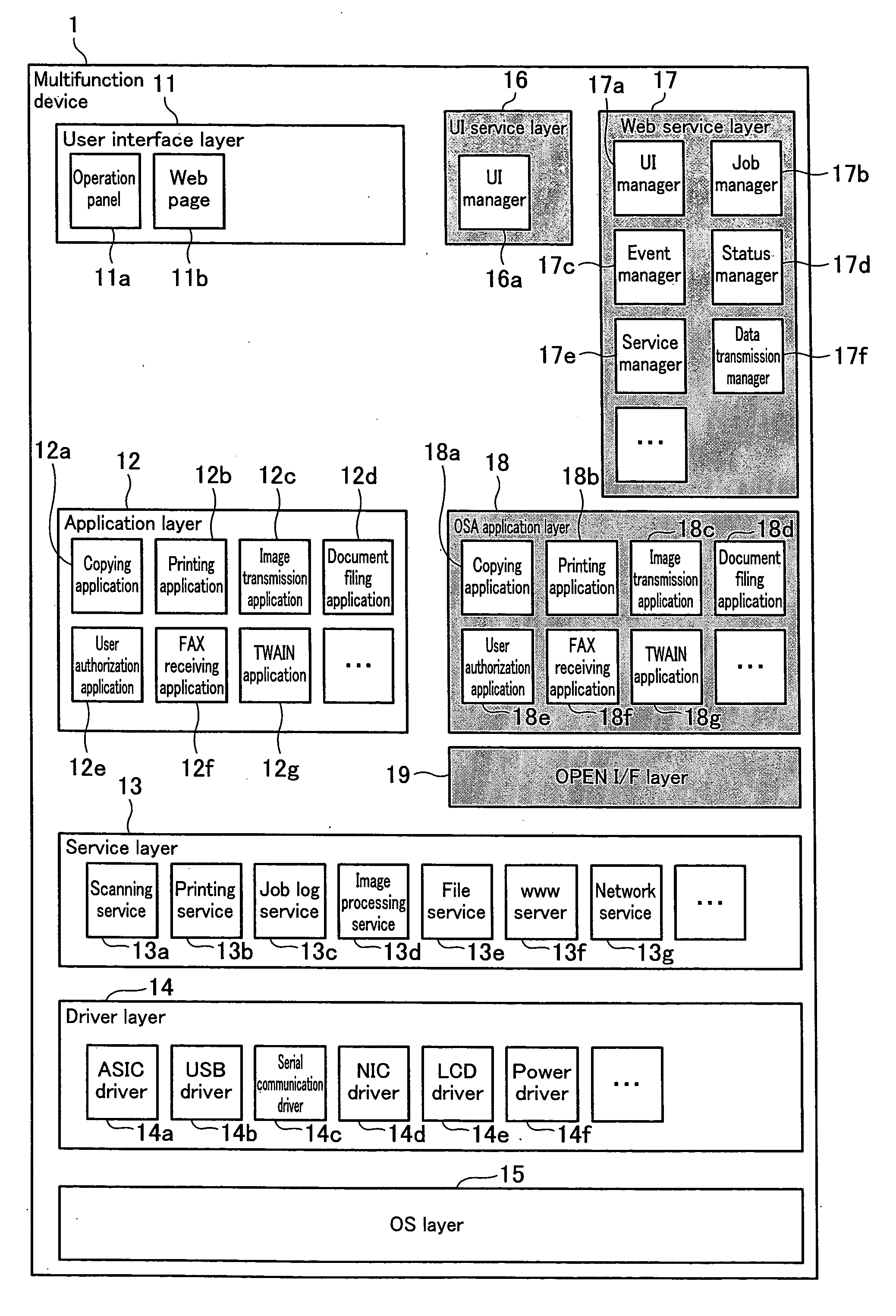
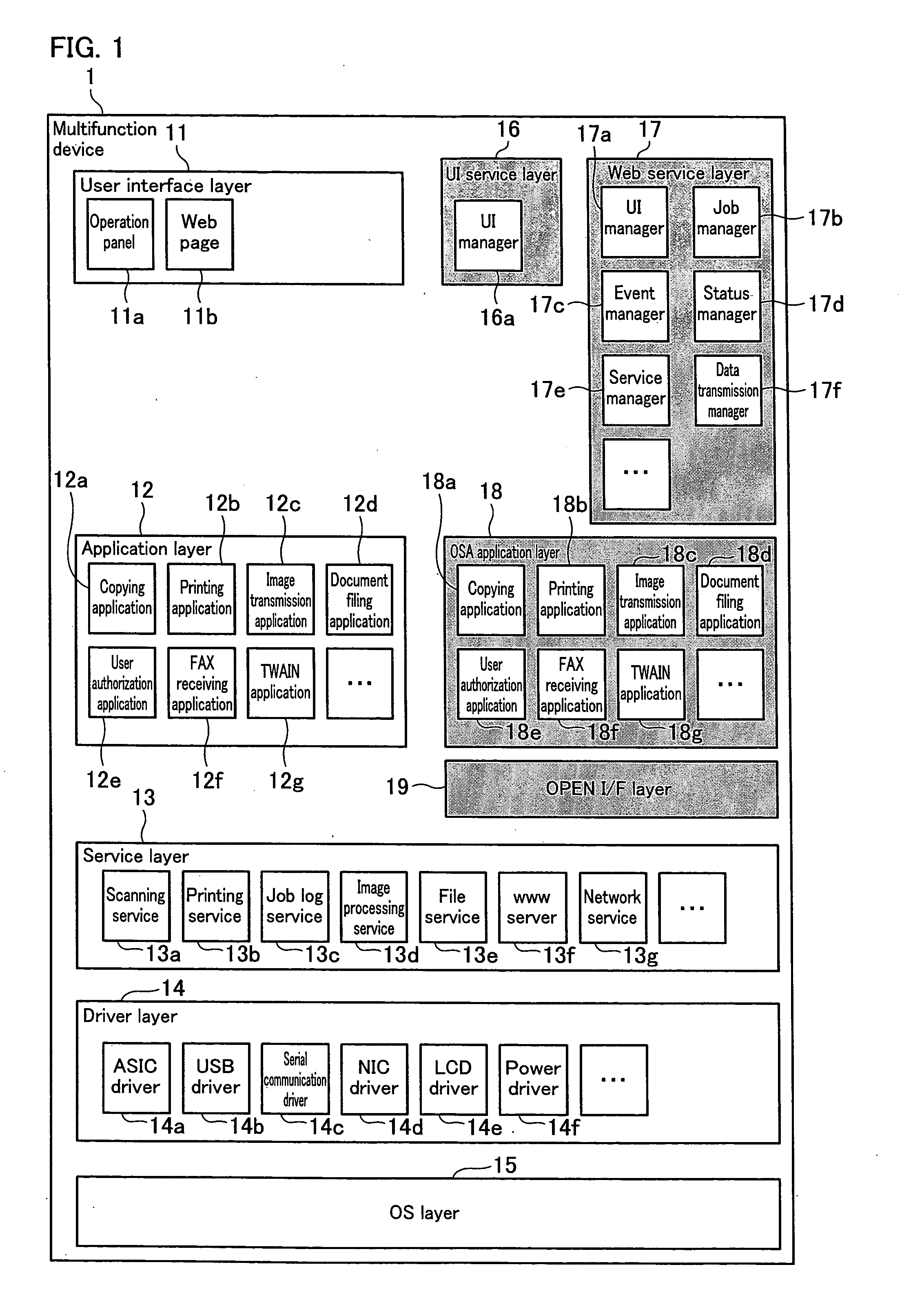
A multifunction device achieves a device function by appropriately combining plural elemental functions including a scanning function, a printing function, and a communication function. The multifunction device includes: a service layer for executing the plural elemental functions; an API table storage section which stores an API table in which a first API for executing the device function is associated with a second API that the service layer can receive; and an Open I / F layer which receives the first API, specifies, in the API table, the second API corresponding to the first API, and outputs the specified second API to the service layer. With this arrangement, it is possible to provide a multifunction device which allows new control from a control device to the multifunction device to be easily developed.

Description

[0001] This Nonprovisional application claims priority under 35 U.S.C. § 119(a) on Patent Application No. 370913 / 2005 filed in Japan on Dec. 22, 2005, the entire contents of which are hereby incorporated by reference. FIELD OF THE INVENTION [0002] The present invention relates to a multifunction device which achieves device functions by appropriately combining and executing elemental functions including an image reading function, an image forming function, and a communication function. BACKGROUND OF THE INVENTION [0003] Multifunction devices having functions of a photocopier, scanner, printer, facsimile machine and the like have been known. In the meanwhile, along with the development of communication networks, there has been such a technology that the multifunction device is connected to a control device constituted by a personal computer (PC) via a communication network, the control device supplies document data to the multifunction device, and the multifunction device forms a doc...

Claims


Application Information

Patent Timeline
IPC IPC(8): H04N1/40
CPCG06F9/485H04N1/00204H04N1/00416H04N1/00973H04N2201/0094H04N2201/0039H04N2201/0046H04N2201/0074H04N2201/0015
Inventor TSUJIMOTO, KUNIHIKO
Owner SHARP KK
Learn More