Centrifugal fan and fan frame thereof

a centrifugal fan and fan frame technology, applied in the direction of machines/engines, combination engines, liquid fuel engines, etc., can solve the problems of reducing reliability, reducing airflow, and reducing the practicality of air supply on both sides, so as to enhance the efficiency of the fan and increase the airflow

Inactive Publication Date: 2007-07-12
DELTA ELECTRONICS INC
View PDF14 Cites 26 Cited by
  • Summary
  • Abstract
  • Description
  • Claims
  • Application Information

AI Technical Summary

Benefits of technology

[0011] As mentioned above, a centrifugal fan and a fan frame thereof according to the present invention have two independent airflow passages. Therefore, the airflows can be increased to enhance the efficiency of the fan. In addition, the two independent airflow passages can be adjusted to have applicable flexibility for example different airflow rates and directions.

Problems solved by technology

As electronic products increase in performance, operating frequencies, speed and compactness, their working temperature also increases to reduce their reliability.
However, the air: supplying conditions on both sides are different in practicality, and there is only a single outlet.
So that the airflows entering from the inlets interfere with each other, and the heat dissipation effect of the fan is affected.

Method used


Image

  • Centrifugal fan and fan frame thereof
  • Centrifugal fan and fan frame thereof
  • Centrifugal fan and fan frame thereof

Examples


Embodiment Construction

[0018] The present invention will be apparent from the following detailed description, which proceeds with reference to the accompanying drawings, wherein the same references relate to the same elements.

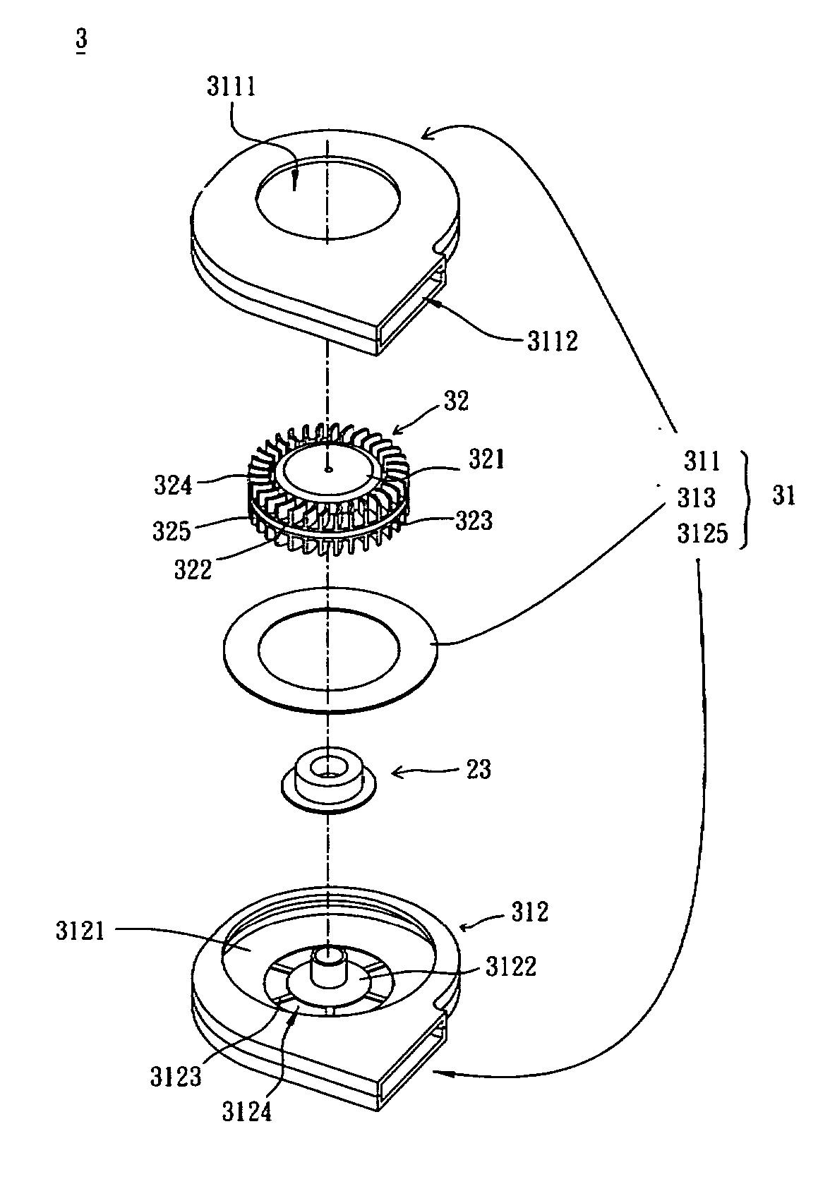
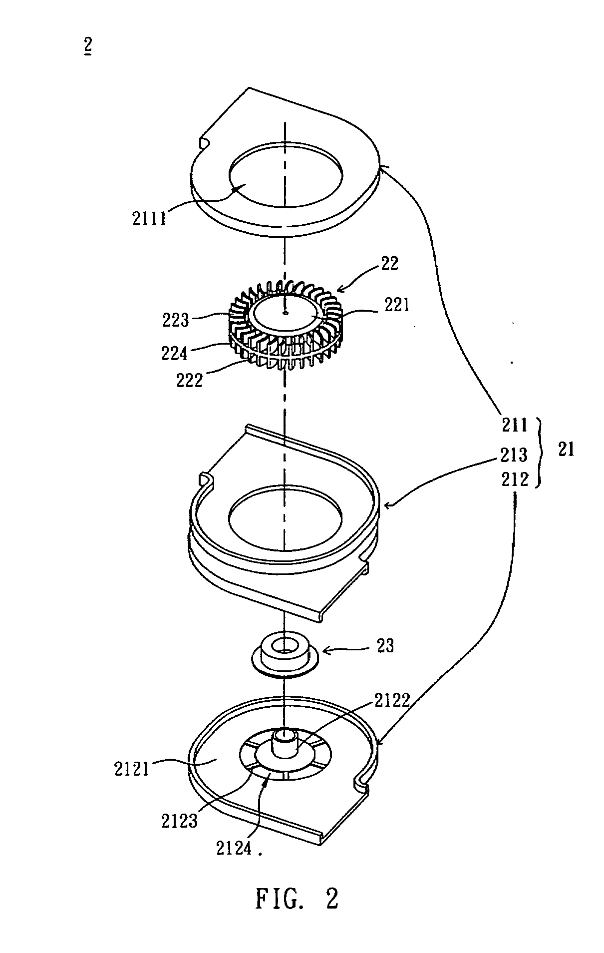
[0019] As shown in FIGS. 2 and 3, a centrifugal fan 2 according to a preferred embodiment of the present invention includes a fan frame 21, at least one impeller 22 and a motor 23. The fan frame 21 includes two housings 211, 212 and a separation part 213. The motor 23 is disposed on the housings 211, 212 or the separation part 213. In this embodiment, the motor 23 for example but not limited to be is disposed on the housing 212.

[0020] The housing 211 has an inlet 2111, and the housing 212 has an inlet 2124. The separation part 213 is disposed between the housing 211 and the housing 212, and respectively connected to the housings 211, 212 to form two independent airflow passages and two outlets 2112, 2125. The separation part 213 and the housings 211, 212 can be independently formed...


PUM


Abstract

A fan frame includes a first housing and a second housing. The first housing has at least one first inlet, and the second housing has at least one second inlet. The combination of the first housing and the second housing forms two independent airflow passages, at least one first outlet and at least one second outlet. A centrifugal fan including the fan frame is also disclosed.

Description

BACKGROUND OF THE PRESENT INVENTION [0001] 1. Field of Invention [0002] The present invention relates to a centrifugal fan, and more particularly to a centrifugal fan with multiple outlets. [0003] 2. Related Art [0004] As electronic products increase in performance, operating frequencies, speed and compactness, their working temperature also increases to reduce their reliability. This is why most of the existing electronic devices use fans to dissipate heat. [0005] As shown in FIG. 1, a conventional centrifugal fan 1 includes a fan frame 11, an impeller 12 and a motor (not shown). The fan frame 11 has a single inlet 111 and a single outlet 112. The impeller 12 is disposed in the fan frame 11 and has a hub 121 and a plurality of blades 122. The motor is disposed in and connected to the hub 121 for driving the impeller 12 to rotate. As the impeller 12 rotates, airflow enters via the inlet 111, gets pushed by the blades 122, and leaves via the outlet 112. [0006] Since the conventional ...

Claims


Application Information

Patent Timeline
Patent Type & Authority Applications(United States)
IPC IPC(8): F04D13/12
CPCF04D29/4246
Inventor TSANG, CHUNG-YUANHUANG, WEN-SHICHIU, YUNG-YU
Owner DELTA ELECTRONICS INC
Why Eureka
Try Eureka