Method of manufacturing light emitting apparatus

a technology of light emitting apparatus and manufacturing method, which is applied in the manufacture of electric discharge tubes/lamps, cold cathode manufacturing, and the manufacture of electromechanical systems, etc., can solve the problems of inconsistency of luminance and and the difficulty of adjusting the chromaticity of light emitted from the light emitting apparatus

Inactive Publication Date: 2007-07-12
SHINKO ELECTRIC IND CO LTD
View PDF5 Cites 20 Cited by
  • Summary
  • Abstract
  • Description
  • Claims
  • Application Information

AI Technical Summary

Problems solved by technology

However, there is a problem of inconsistency of luminance and chromaticity of the light emitted from the light emitting apparatus due to, for example, inconsistency of the characteristics among light emitting devices (more specifically, luminance and chromaticity) and inconsistency of the thickness of the fluorophor.
Therefore, it is difficult to adjust the chromaticity of the light emitted from the light emitting apparatus 100.

Method used


Image

  • Method of manufacturing light emitting apparatus
  • Method of manufacturing light emitting apparatus
  • Method of manufacturing light emitting apparatus

Examples


Embodiment Construction

[0022]In the following, embodiments of the present invention will be described with reference to the accompanying drawings.

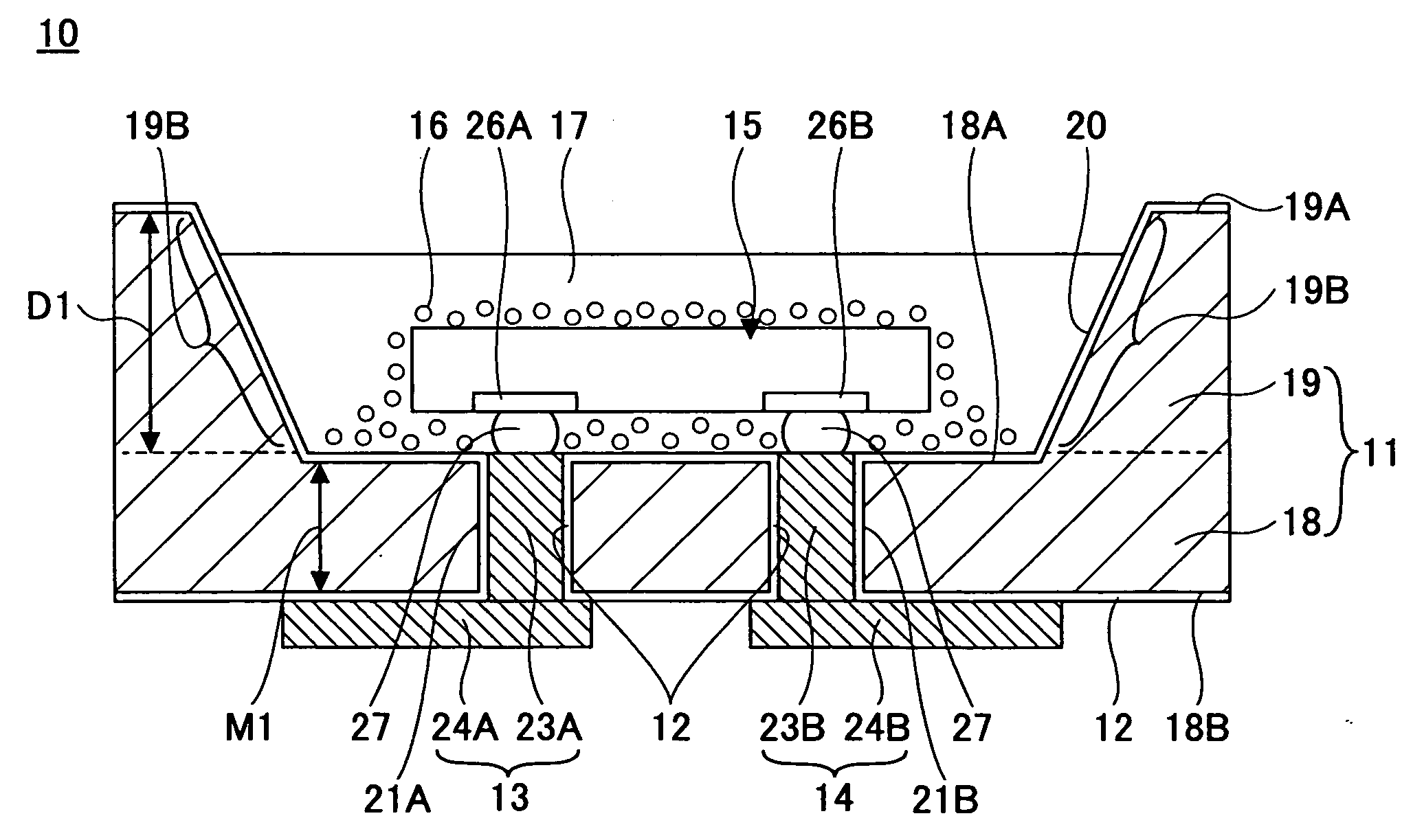
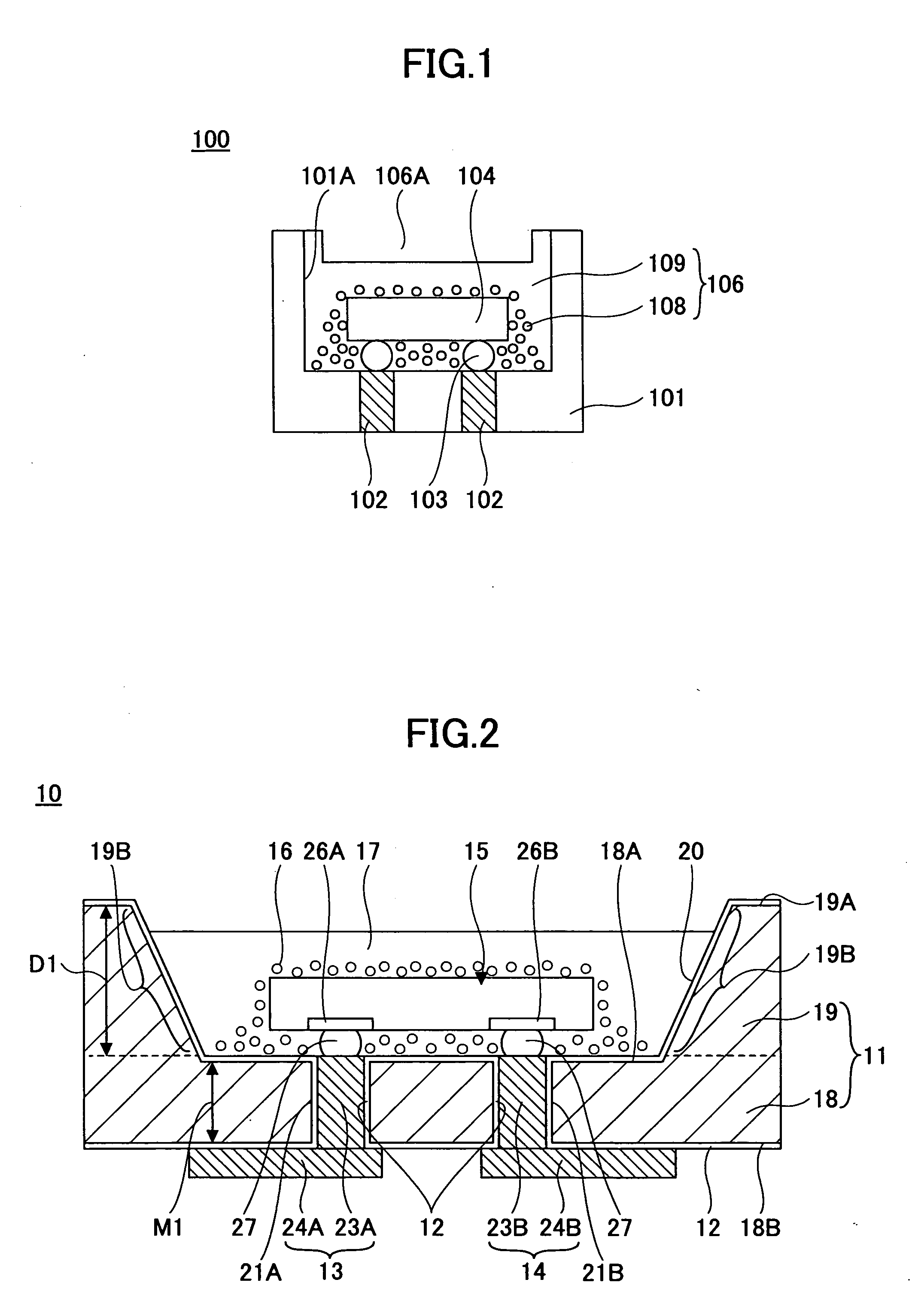
[0023]FIG. 2 is a cross-sectional view showing a light emitting apparatus 10 according to an embodiment of the present invention.

[0024]In FIG. 2, the light emitting apparatus 10 according to an embodiment of the present invention includes a light emitting device installing body 11, a insulating film 12, wiring patterns 13, 14, a light emitting device 15, fluorophor particles 16, and a transparent resin 17.

[0025]The light emitting device installing body 11 includes a plane part 18, a frame part 19, and a concave part 20. The plane part 18 is for supporting the frame part 19. The plane part 18 and the frame part 19 are integrally formed, that is, formed as a united body. The plane part 18 includes plural penetrating holes 21A, 21B. The plane part 18 can be formed having a thickness M1 of, for example, 200 μm. The frame part 19 is provided on top of the plane part ...


PUM


Abstract

A method of manufacturing a light emitting apparatus including a light emitting device and a light emitting device installing body having a concave part for installing the light emitting device therein is disclosed. The method includes the steps of a) forming a coating of plural fluorophor particles covering the light emitting device installed in the concave part, and b) forming a transparent resin covering the plural fluorophor particle coating. Step b) includes a step of performing illumination with the light emitting device so that the light emitted from the light emitting apparatus has a predetermined luminance and chromaticity.

Description

BACKGROUND OF THE INVENTION[0001]1. Field of the Invention[0002]The present invention generally relates to a light emitting apparatus, and more particularly to a method of manufacturing a light emitting apparatus for facilitating adjustment of luminance and chromaticity of the light emitting apparatus.[0003]2. Description of the Related Art[0004]For a light emitting apparatus, it is essential for the light of its light emitting device transmitted through a fluorophor (light emitted from the light emitting apparatus) to have a predetermined luminance and chromaticity. However, there is a problem of inconsistency of luminance and chromaticity of the light emitted from the light emitting apparatus due to, for example, inconsistency of the characteristics among light emitting devices (more specifically, luminance and chromaticity) and inconsistency of the thickness of the fluorophor. One example of the light emitting apparatus having its chromaticity adjusted is shown in FIG. 1.[0005]FI...

Claims


Application Information

Patent Timeline
Patent Type & Authority Applications(United States)
IPC IPC(8): H01J9/26H01J9/32H01L33/50H01L33/56H01L33/62
CPCH01L2933/0041H01L33/50H01L24/97H01L2224/16225H01L2924/181H01L2924/00012
Inventor TAGUCHI, YUICHISHIRAISHI, AKINORIMURAYAMA, KEIKOIZUMI, NAOYUKISUNOHARA, MASAHIROSAKAGUCHI, HIDEAKIHIGASHI, MITSUTOSHI
Owner SHINKO ELECTRIC IND CO LTD
Why Eureka
Try Eureka