Therapeutic ultrasound system

a technology of ultrasound and transmission device, applied in the field of medical equipment, can solve the problems of increasing the fatigue experienced by the transmission wire at certain critical locations, affecting the connection, and affecting the operation of the system, so as to achieve the effect of improving the connection

Inactive Publication Date: 2007-07-12
FLOWCARDIA
View PDF3 Cites 18 Cited by
  • Summary
  • Abstract
  • Description
  • Claims
  • Application Information

AI Technical Summary

Benefits of technology

[0012] It is an object of the present invention to provide an ultrasound device that provides an improved connection between the ultrasound transmission member and the transducer.

Problems solved by technology

However, all of these systems and devices generally encounter some problems.
A first type of problem relates generally to the effective transmission of ultrasound energy from an ultrasound source to the distal tip of the device where the ultrasound energy is applied to ablate or remove obstructive material.
This transmission of increased energy along the transmission wire may increase the fatigue experienced by the transmission wire at certain critical locations, such as at the connection between the transducer and the transmission wire.
A second type of problem relates to the breakage of the ultrasound transmission member which extends through such catheters.
Because of its small diameter, the ultrasound transmission member is particularly susceptible to breakage.
In addition, significant amounts of heat can build up along the length of the ultrasound transmission member, and excessive heat can damage the integrity of the ultrasound transmission member.
A third type of problem relates to the need for accurately positioning the ultrasound device inside a patient's vasculature, and in particular, where the vasculature contains smaller and more tortuous vessels.
However, these devices have not been completely satisfactory in meeting these navigational needs.
A fourth type of problem relates to the actual ablation of the obstructive material.
A fifth type of problem relates to the removal of particles that are produced when the obstructive material is ablated or broken up.

Method used


Image

  • Therapeutic ultrasound system
  • Therapeutic ultrasound system
  • Therapeutic ultrasound system

Examples


Embodiment Construction

[0035] The following detailed description is of the best presently contemplated modes of carrying out the invention. This description is not to be taken in a limiting sense, but is made merely for the purpose of illustrating general principles of embodiments of the invention. The scope of the invention is best defined by the appended claims. In certain instances, detailed descriptions of well-known devices, compositions, components, mechanisms and methods are omitted so as to not obscure the description of the present invention with unnecessary detail.

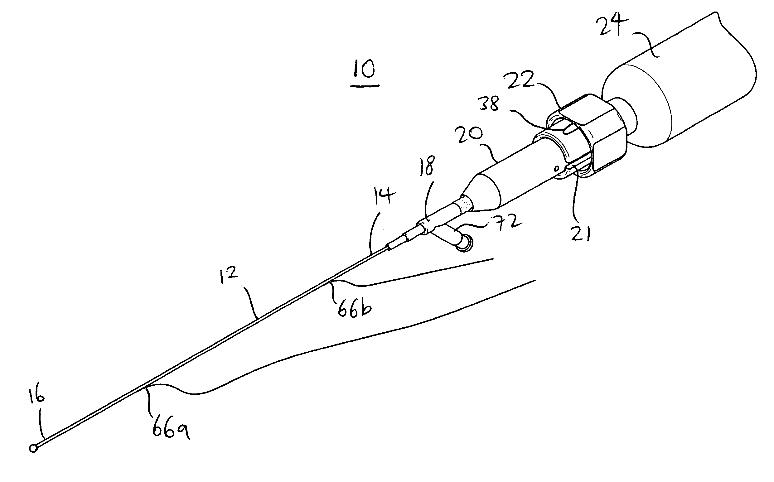
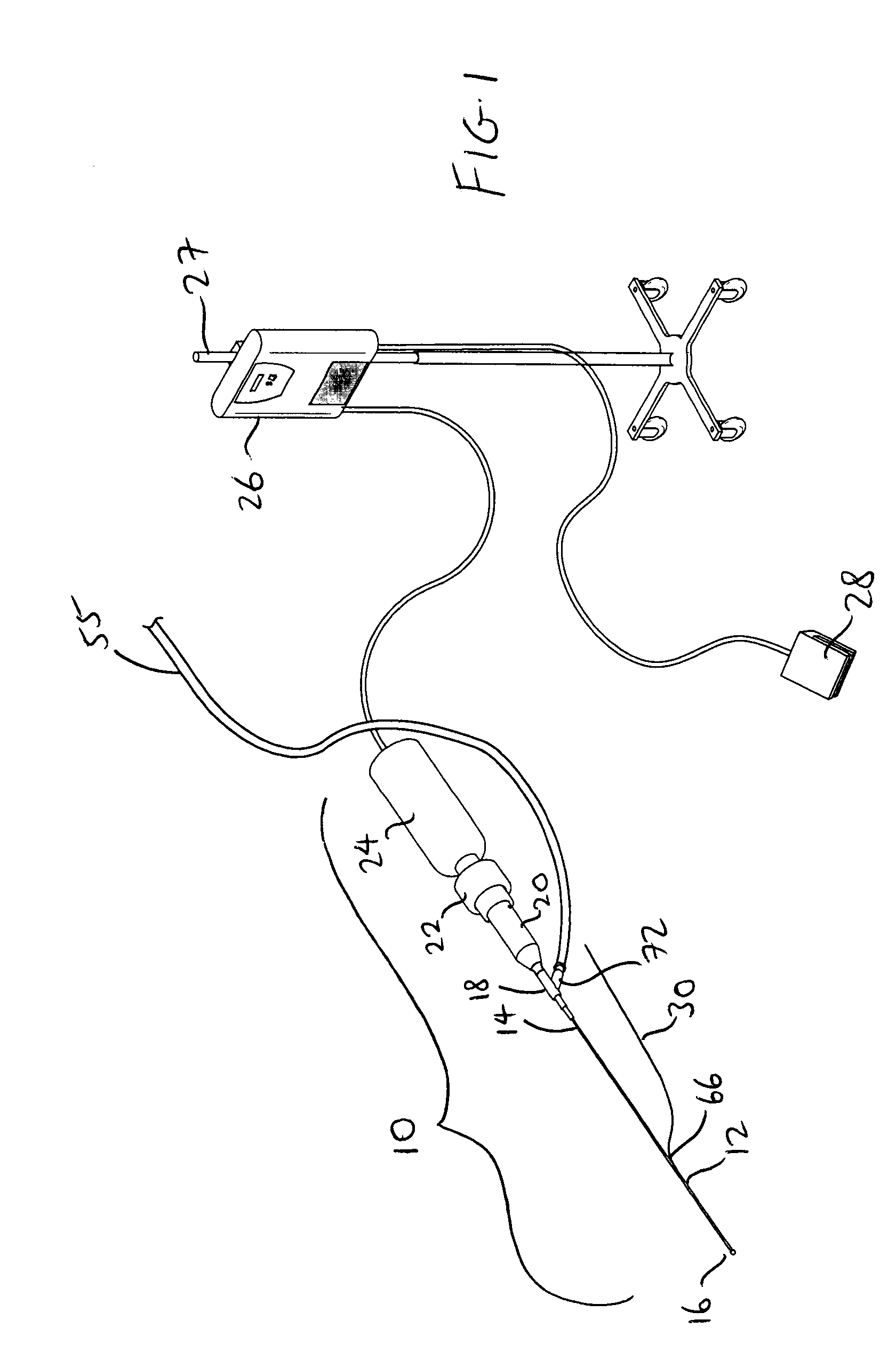
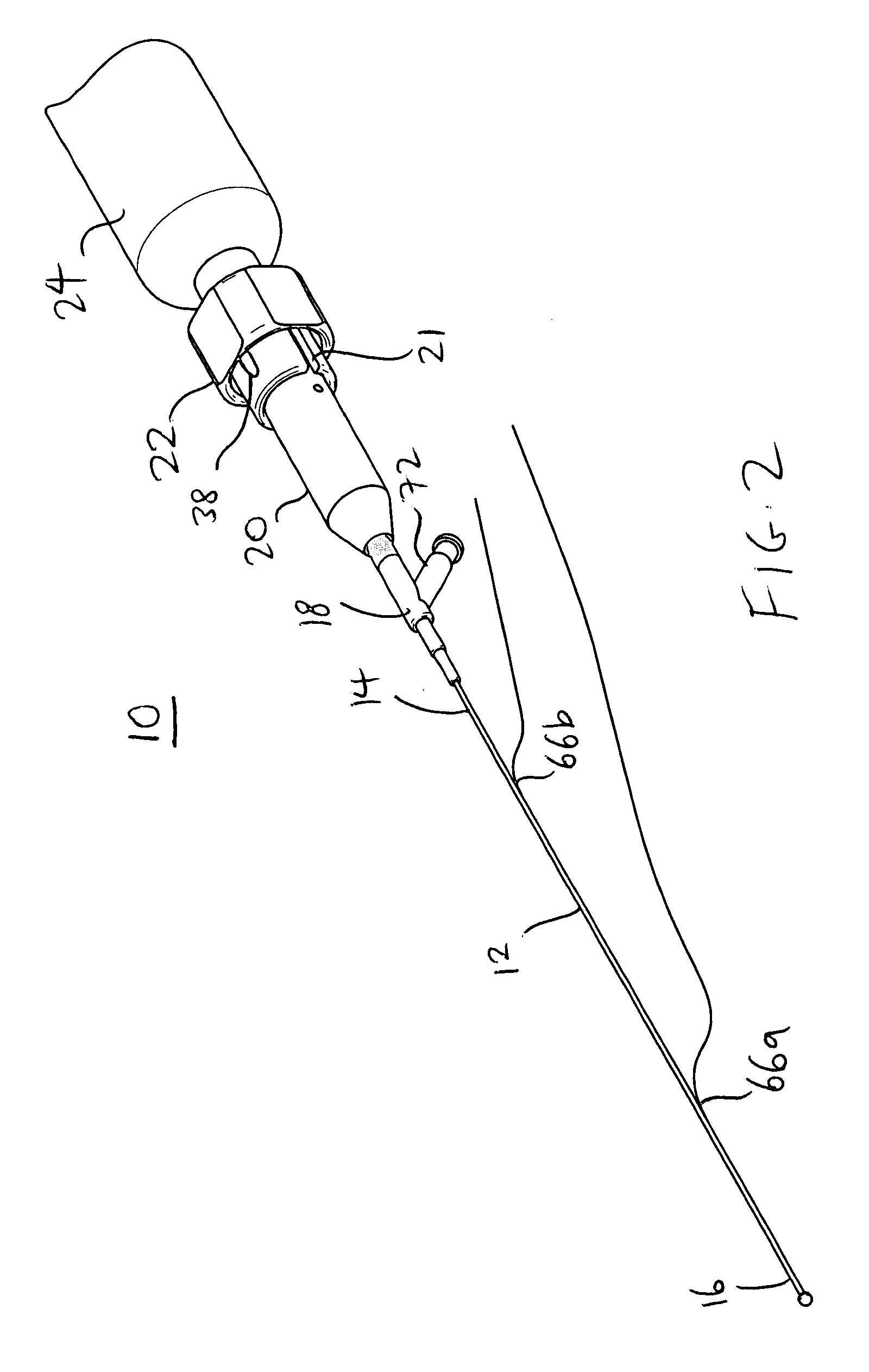
[0036]FIGS. 1 and 2 illustrate an ultrasound system according to the present invention for use in ablating and removing occlusive material inside the vessel of an animal or human being. The ultrasound system includes an ultrasonic catheter device 10 which has an elongate catheter body 12 having a proximal end 14, a distal is end 16, and defining at least one lumen extending longitudinally therethrough. The ultrasound catheter device 1...


PUM


Abstract

An ultrasound system has a catheter including an elongate flexible catheter body having a main lumen extending longitudinally therethrough. The catheter further includes an ultrasound transmission member extending longitudinally through the main lumen of the catheter body, the ultrasound transmission member having a proximal end connectable to an ultrasound generating device and a distal end coupled to the distal end of the catheter body.

Description

RELATED CASES [0001] This is a continuation-in-part of co-pending Ser. No. 10 / 211,418, filed Aug. 2, 2002, entitled “Therapeutic Ultrasound System”, and co-pending Ser. No. 09 / 251,227, filed Sep. 20, 2002, entitled “Connector For Securing Ultrasound Catheter to Transducer”, the entire disclosures of which are incorporated by this reference as though set forth fully herein.BACKGROUND OF THE INVENTION [0002] 1. Field of the Invention [0003] The present invention pertains to medical equipment, and more particularly, to a therapeutic ultrasound system and methods used therewith for ablating obstructions within tubular anatomical structures such as blood vessels. [0004] 2. Description of the Prior Art [0005] A number of ultrasound systems and devices have heretofore been proposed for use in ablating or removing obstructive material from blood vessels. Ultrasound catheters have been utilized to ablate various types of obstructions from blood vessels of humans and animals. Successful appli...

Claims


Application Information

Patent Timeline
Patent Type & Authority Applications(United States)
IPC IPC(8): A61B17/20A61B17/22
CPCA61B17/22004A61B17/22012A61B17/2202A61B2017/00331A61B2017/0046A61B2017/00477A61B2019/528A61B2017/22014A61B2017/22015A61B2017/22038A61B2017/22039A61B2017/320088A61B2017/00867A61B2090/3784
Inventor NITA, HENRYSARGE, JEFF
Owner FLOWCARDIA
Why Eureka
Try Eureka