Bone anchoring device

a technology of bone anchoring and rod, which is applied in the field of bone anchoring devices, can solve the problems of loosening of the fixation, limiting the possibility of adjustment of the position of the shaft relative to the rod, and difficult adjustment and time-consuming, and achieves the effect of improving the locking of the rod

Inactive Publication Date: 2007-07-12
BIEDERMANN TECH GMBH & CO KG
View PDF8 Cites 235 Cited by
  • Summary
  • Abstract
  • Description
  • Claims
  • Application Information

AI Technical Summary

Benefits of technology

[0006] During tightening of the closure element of the bone anchoring device according to the present disclosure, the deformation of the elastic material of the rod leads to a form-fit connection between the elastic rod and the receiving part. This

Problems solved by technology

When using a flexible rod made of an elastic material with such a bone screw, the pressure exerted by the inner fixation screw onto the rod would cause a deformation of the elastic material which could result in loosening of the fixation.
Thi

Method used


Image

  • Bone anchoring device
  • Bone anchoring device
  • Bone anchoring device

Examples


Embodiment Construction

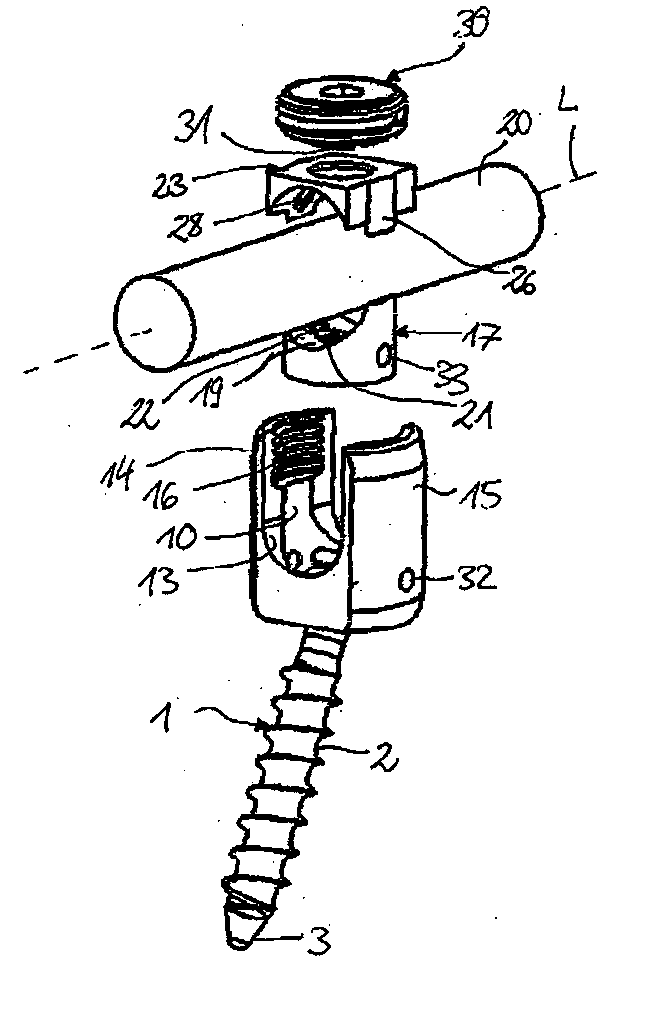
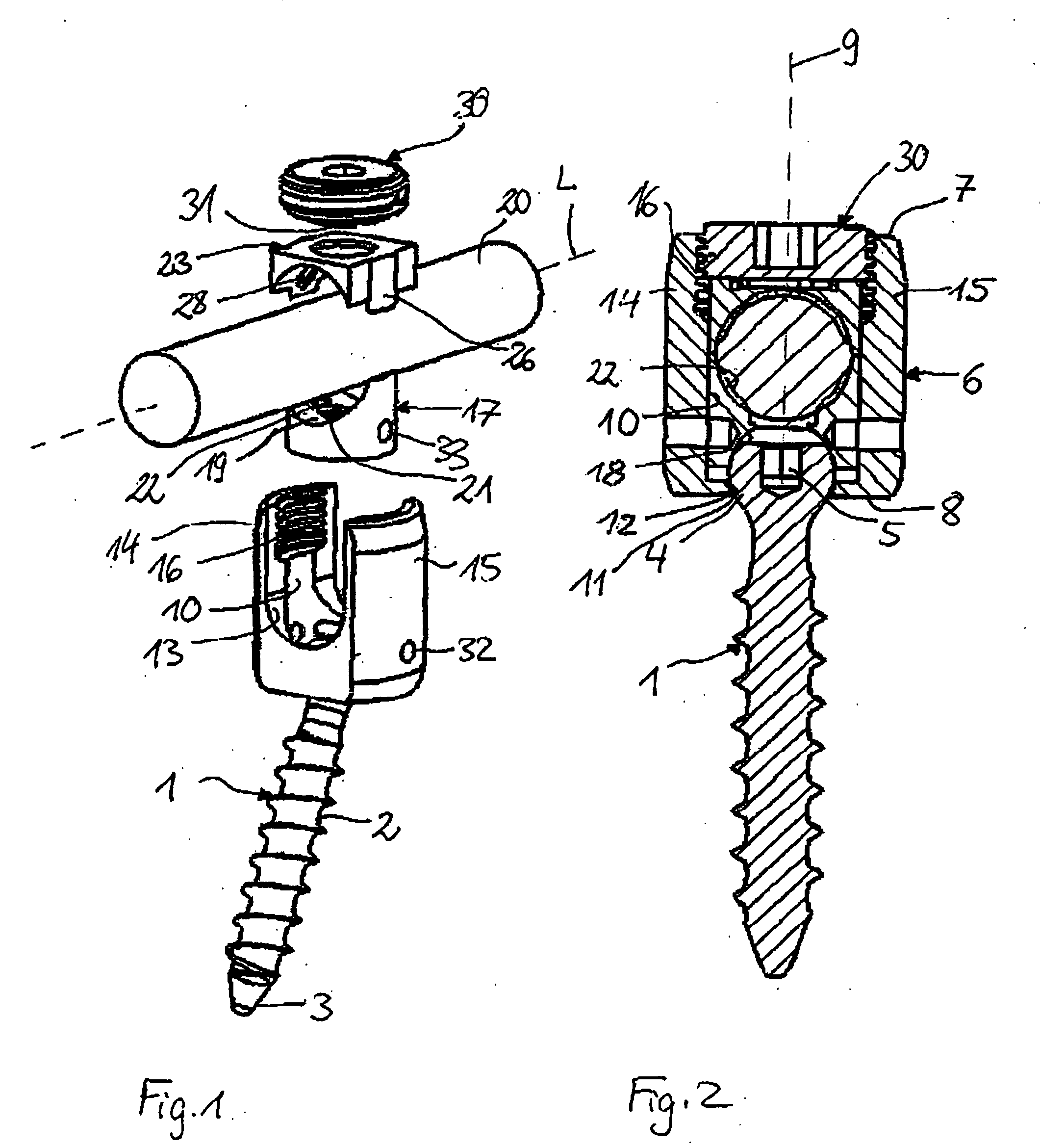
[0017] As shown in FIGS. 1 and 2, the bone anchoring device comprises a bone anchoring element 1 in the form of a bone screw having a shank 2 with a bone thread, a tip 3 at one end and a spherical head 4 at the opposite end. A recess 5 for engagement with a screwing-in tool is provided at the side of the head 4 which is opposite to the shank 2.

[0018] The bone anchoring device further includes a receiving part 6 having a first end 7 and a second end 8 opposite to the first end 7 and a longitudinal axis 9 intersecting the plane of the first end 7 and the second end 8. Coaxially with the longitudinal axis 9 a bore 10 is provided which extends from the first end 7 to a predetermined distance from the second end 8. At the second end 8 an opening 11 is provided the diameter of which is smaller than the diameter of the bore 10. A spherical section 12 is provided adjacent of the opening 10 which forms a seat for the spherical head 4.

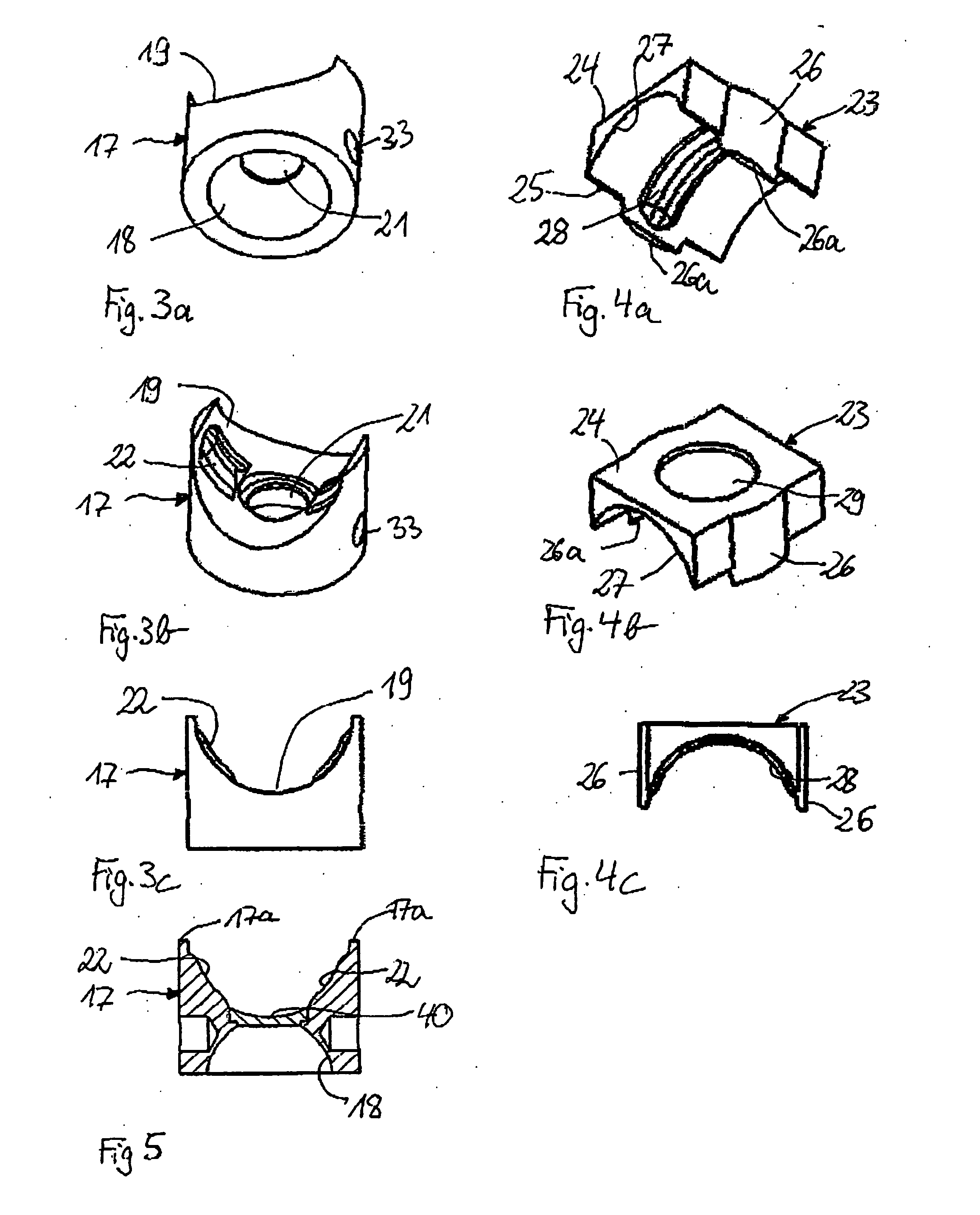
[0019] The receiving part 6 further has a U-shaped reces...


PUM


Abstract

A bone anchoring device includes an anchoring element having a shank to be anchored in a bone or a vertebra and a head, a connection element for connecting at least two anchoring elements, a receiving part having a first end receiving the head, wherein the head is pivotable in the receiving part, and a second end comprising a recess for receiving the connection element, a first pressure element which exerts pressure on the head to lock the head in the receiving part, and a second pressure element which exerts pressure on the connection element to press the connection element against the first pressure element. The contour of the surface of at least the first pressure element or the second pressure element facing the connection element deviates from the contour of the surface of the connection element.

Description

CROSS-REFERENCE TO RELATED APPLICATION(S) [0001] The present disclosure claims the benefit of U.S. Provisional Patent Application Ser. No. 60 / 738,007, filed Nov. 17, 2005, and claims priority from European Patent Application EP05025161.0, filed Nov. 17, 2005, the entire disclosures of which are incorporated herein by reference.FIELD OF DISCLOSURE [0002] The present invention relates to a bone anchoring device for the dynamic stabilization of bones in particular for the dynamic stabilization of the spine. It includes a bone anchoring element which can be connected with a flexible rod made of an elastic material and allows a polyaxial adjustment of the position of the anchoring element relative to the rod. BACKGROUND [0003] A polyaxial bone screw to be connected with a stiff rod, usually made of metal, is known from DE 43 07 576 C1. When using a flexible rod made of an elastic material with such a bone screw, the pressure exerted by the inner fixation screw onto the rod would cause a ...

Claims


Application Information

Patent Timeline
IPC IPC(8): A61F2/30
CPCA61B17/7031A61B17/7037A61B17/7032A61B17/58A61B17/68A61B17/84
Inventor BIEDERMANN, LUTZMATTHIS, WILFRIED
Owner BIEDERMANN TECH GMBH & CO KG
Why Eureka
Try Eureka