
Method for storing plant process signals

Inactive Publication Date: 2007-07-12
SIEMENS AG
View PDF36 Cites 5 Cited by
  • Summary
  • Abstract
  • Description
  • Claims
  • Application Information

AI Technical Summary

Benefits of technology

[0010] The object of the invention is therefore to specify an improved method for storing plant process signals which has a reduced storage space requirement and for which in particular any loss of important information contained in the process signals is avoided.

Problems solved by technology

Conserving storage resources therefore necessarily means losing information.

Method used


Image

  • Method for storing plant process signals
  • Method for storing plant process signals

Examples


Embodiment Construction

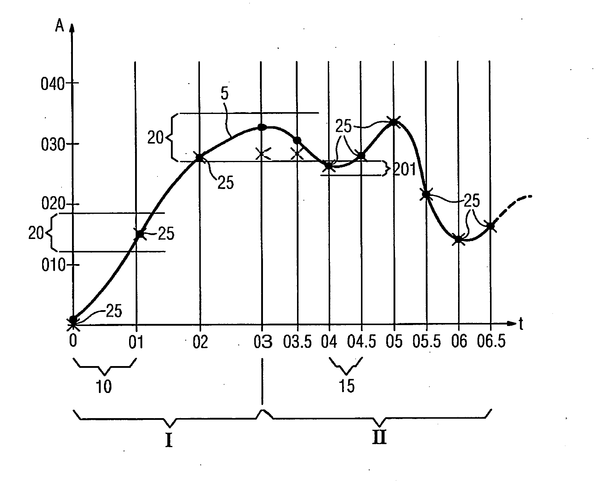
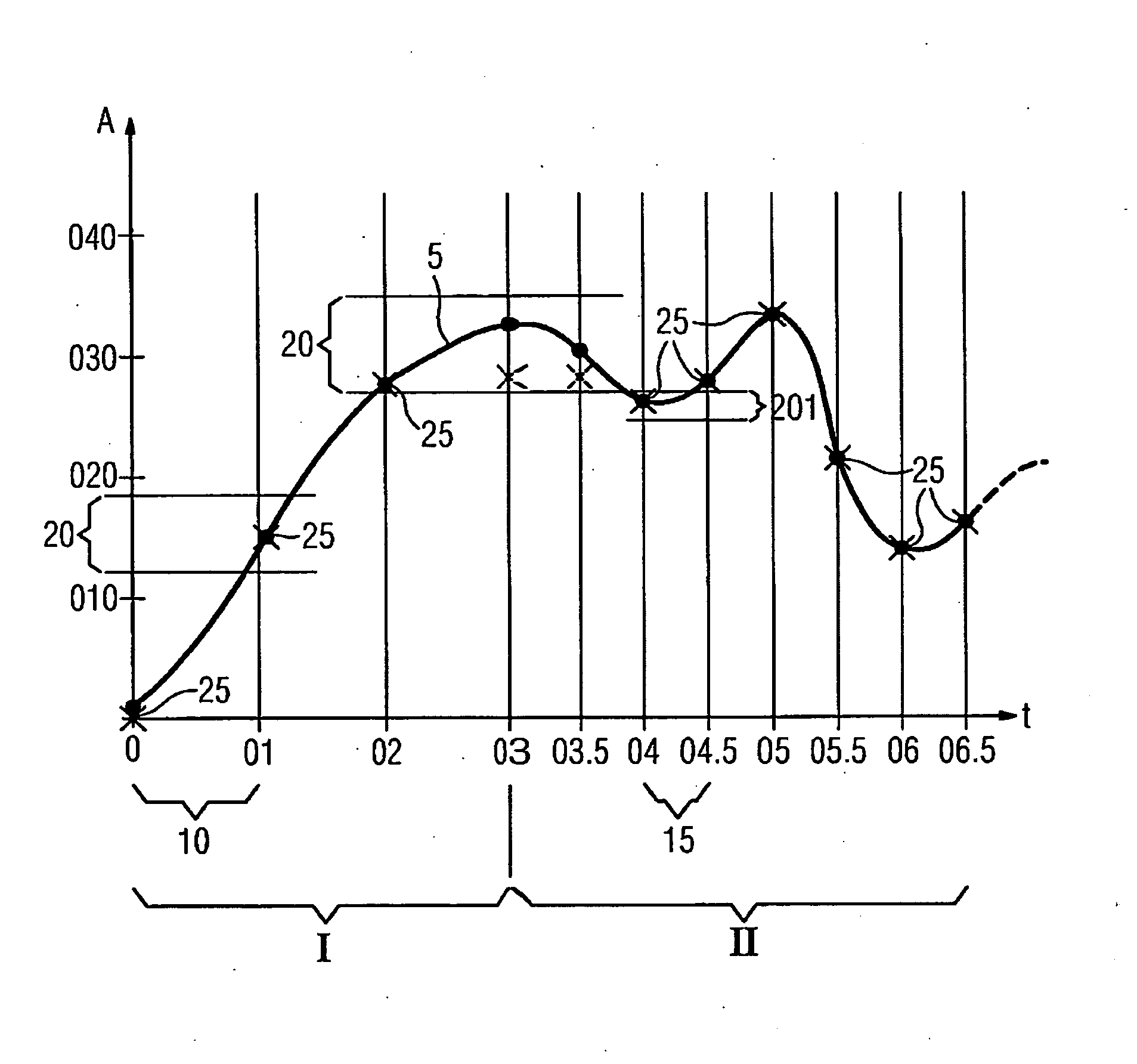
[0052] The figure shows a process signal 5 which changes over time.

[0053] During the period t=0 to t=03 the process signal 5 increases from a near 0 value to a value in the region of 030, the increase in the process signal 5 being continuous and no or only small oscillations or increase variations occurring.

[0054] From instant t=03 onwards the process signal 5 tends to oscillations and more pronounced amplitude variations. In the case of a plant, for example, this could be caused by a load alternation occurring at instant t=03.

[0055] This operating state is indicated by reference numeral II in the figure; the previous operating state during which the value of the process signal 5 varies less markedly and represents, for example, normal startup of the plant is indicated by reference numeral I.

[0056] The time response of the process signal 5 is denoted as signal amplitude A.

[0057] During the period of operating state I, the signal amplitude A of the process signal 5 is sampled at...


PUM


Abstract

Disclosed is a method for storing process signals of a plant or technical installation. A compression method is adapted for a current operating state of the plant is applied to the set of process signals in accordance with the current operating state of the plant and a compressed process signal set which is determined during the application of the compression method is stored.

Description

CROSS REFERENCE TO RELATED APPLICATIONS [0001] This application is the US National Stage of International Application No. PCT / EP2004 / 053555, filed Dec. 17, 2004 and claims the benefit thereof. The International Application claims the benefits of European application No. 04001690.9 EP filed Jan. 27, 2004, both of the applications are incorporated by reference herein in their entirety. FIELD OF INVENTION [0002] The invention relates to a method for storing plant process signals wherein, during operation of the plant, a number of process signals associated with the various processes are produced which are to be fed to a storage device. BACKGROUND OF INVENTION [0003] In order to be able to assess the behavior of a plant during operation or retrospectively, it is necessary to store a mostly large number of process signals produced during operation and to analyze their characteristics as function of time. [0004] These process signals usually originate from different components and must be...

Claims


Application Information

Patent Timeline
IPC IPC(8): G06G7/70G06F19/00G05B21/02G05B23/02H03M1/12H03M7/30
CPCG05B21/02H03M7/30H03M1/127G05B23/0264
Inventor BODE, ANDREASHEMPL, MARTIN
Owner SIEMENS AG
Learn More