Markers, methods of marking, and marking systems for use in association with images

a technology of marking system and image, which is applied in the field of marking system for use in association with images, can solve the problems of affecting the reading of the book

Inactive Publication Date: 2007-07-19
RUSSELL DONALD G
View PDF2 Cites 14 Cited by
  • Summary
  • Abstract
  • Description
  • Claims
  • Application Information

AI Technical Summary

Benefits of technology

[0024] One advantage of currently preferred embodiments of the above aspects of the present invention is that they provide a method f

Problems solved by technology

Often the abnormality is a significant visual abnormality that is immediately evident.
Furthermore, if the surrounding anatomic tissue does not have clearly defined anatomic reference points, a description of the location within said organ may be imprecise and confusing to a second observer.
In addition, marks are sometimes seen as an aberration and/or a disconcerting distraction to the reader, such that the eye of the reader is drawn to the mark during the study of the remainder of the image or during an attempt to compare the marked image to prior films of the same area or to additional or contra lateral views of the same body part.
Moreover, marks made using a wax are not easily removed.
Attempts at removal most often involve time consuming scrubbing of the

Method used


Image

  • Markers, methods of marking, and marking systems for use in association with images
  • Markers, methods of marking, and marking systems for use in association with images
  • Markers, methods of marking, and marking systems for use in association with images

Examples


second embodiment

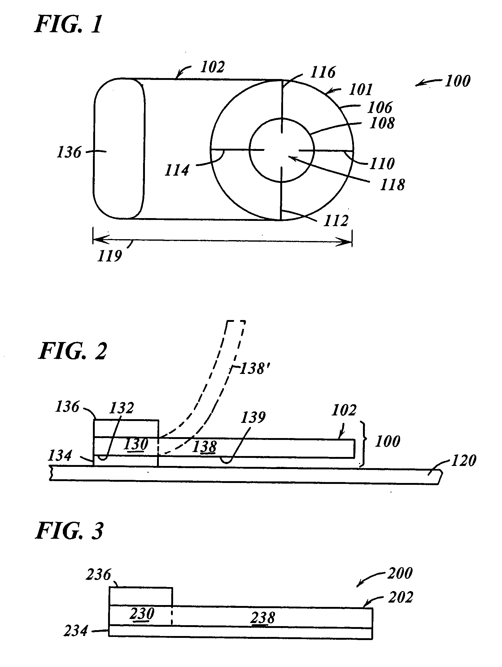
[0079]FIG. 3 shows a side elevational view of a marker 200 according to a The marker 200 is similar to the marker 100 (except where otherwise noted, like reference numerals preceded by the numeral “2” instead of the numeral “1” are used to indicate like elements) except that the adhesive layer 234 of the marker 200 coats the underlying surfaces of both portions 230, 238 of the base 202. Thus, the adhesive layer 234 is preferably comprised of an adhesive that is substantially clear, and more preferably, transparent.

[0080] It should be understood that some other embodiments may employ adhesive on the underside of the second portion but not on the underside of the first portion.

third embodiment

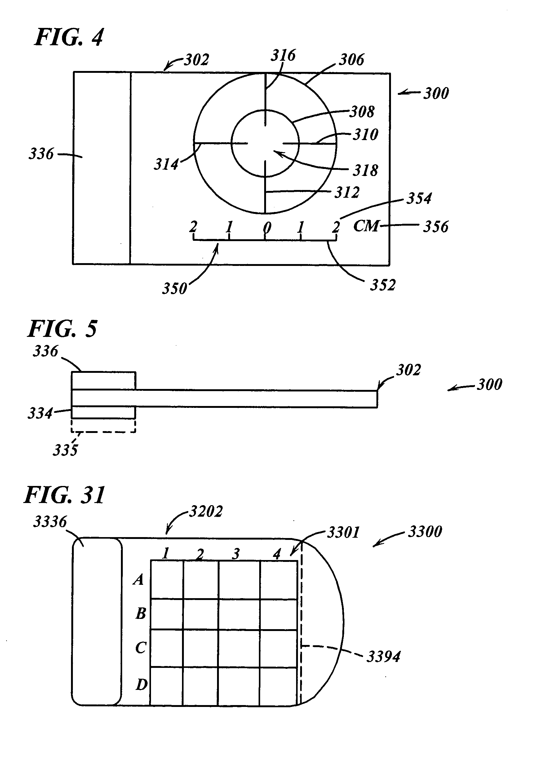
[0081]FIGS. 4-5 show views of a marker 300 according to a The marker 300 is similar to the marker 100 (except where otherwise noted, like reference numerals preceded by the numeral “3” instead of the numeral “1” are used to indicate like elements) except that (i) the base 302 and paper tab 336 of the marker 300 have square corners and are somewhat larger than the base 102 and paper tab 136, respectively, and (ii) the base 302 includes added indicia (compared to the base 102) in the form of a gauge portion 350. The larger base allows a border around the target sight, without the need to reduce the size of the target sight. The gauge portion 350 includes a graduated portion 352, numeric indicia 354 and dimensional indicia 356. This type of gauge portion may be used for example, to determine the size of features appearing in a diagnostic image (e.g., diagnostic image 120 (FIG. 2)). Gauge portions (or any portion thereof) may also be employed on the other markers disclosed herein.

[0082...

fourth embodiment

[0083]FIGS. 6-7 show views of a marker 400 according to a The marker 400 is similar to the marker 100 (except where otherwise noted, like reference numerals preceded by the numeral “4” instead of the numeral “1” are used to indicate like elements) except that the marker 400 does not include a plain paper tab for notes. The first base portion 430 is made translucent or opaque and adapted to receive written notes.


PUM


Abstract

Markers, methods of marking, and marking systems for use in association with images are disclosed. One marker is removable with a targeted design and metric dimensions inscribed on a clear plastic flap. This marker is attached adjacent to an area of interest with the target placed in such a manner to precisely pin point out an observed abnormality. A paper label at one edge is available for written comments and directions for further studies. The marker can be removed without damage to the image(s).

Description

CROSS REFERENCE TO RELATED APPLICATIONS [0001] This application is a continuation of U.S. application Ser. No. 10 / 722,920, filed Nov. 26, 2003, entitled “MARKERS, METHODS OF MARKING, AND MARKING SYSTEMS FOR USE IN ASSOCIATION WITH IMAGES” and to U.S. Provisional Patent Application Ser. No. 60 / 429,943, filed Nov. 29, 2002, entitled “MARKERS AND MARKER METHODS FOR DIAGNOSTIC IMAGES, AND SYSTEMS AND APPARATUS, AND METHODS EMPLOYING SAME”, both of which are herein incorporated by reference in their entirety.RELATED INFORMATION [0002] Diagnostic images in medical practice are often radiographic shadows of anatomic components representing a graphic display of disparate radiographic densities. This array of contrasting anatomic shadows is commonly captured and displayed on a photographic film base for study by an observer on a lighted view box. These are the well known diagnostic radiographs or x-ray studies interpreted by a physician trained in this field as a Radiologist. [0003] Study of...

Claims


Application Information

Patent Timeline
IPC IPC(8): G01B3/10A61B19/00A61NB43L7/00B43L13/20G01B3/14G01B5/04G09F3/04
CPCA61B2019/5437A61B19/54A61B90/39A61B2090/3937
Inventor RUSSELL, DONALD G.
Owner RUSSELL DONALD G
Why Eureka
Try Eureka