Variable valve operating device for engine

a technology of variable valve and operating device, which is applied in the direction of valve details, valve arrangement, valve drive, etc., can solve the problems of responding speed, and achieve the effect of reliable fixing

Inactive Publication Date: 2007-07-19
MIKUNI CORP
View PDF2 Cites 16 Cited by
  • Summary
  • Abstract
  • Description
  • Claims
  • Application Information

AI Technical Summary

Benefits of technology

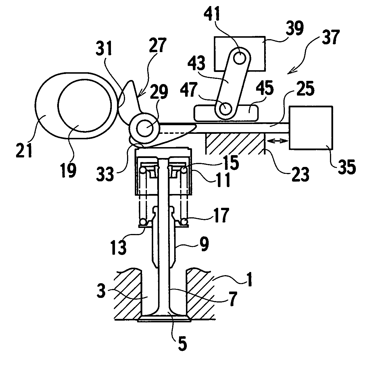
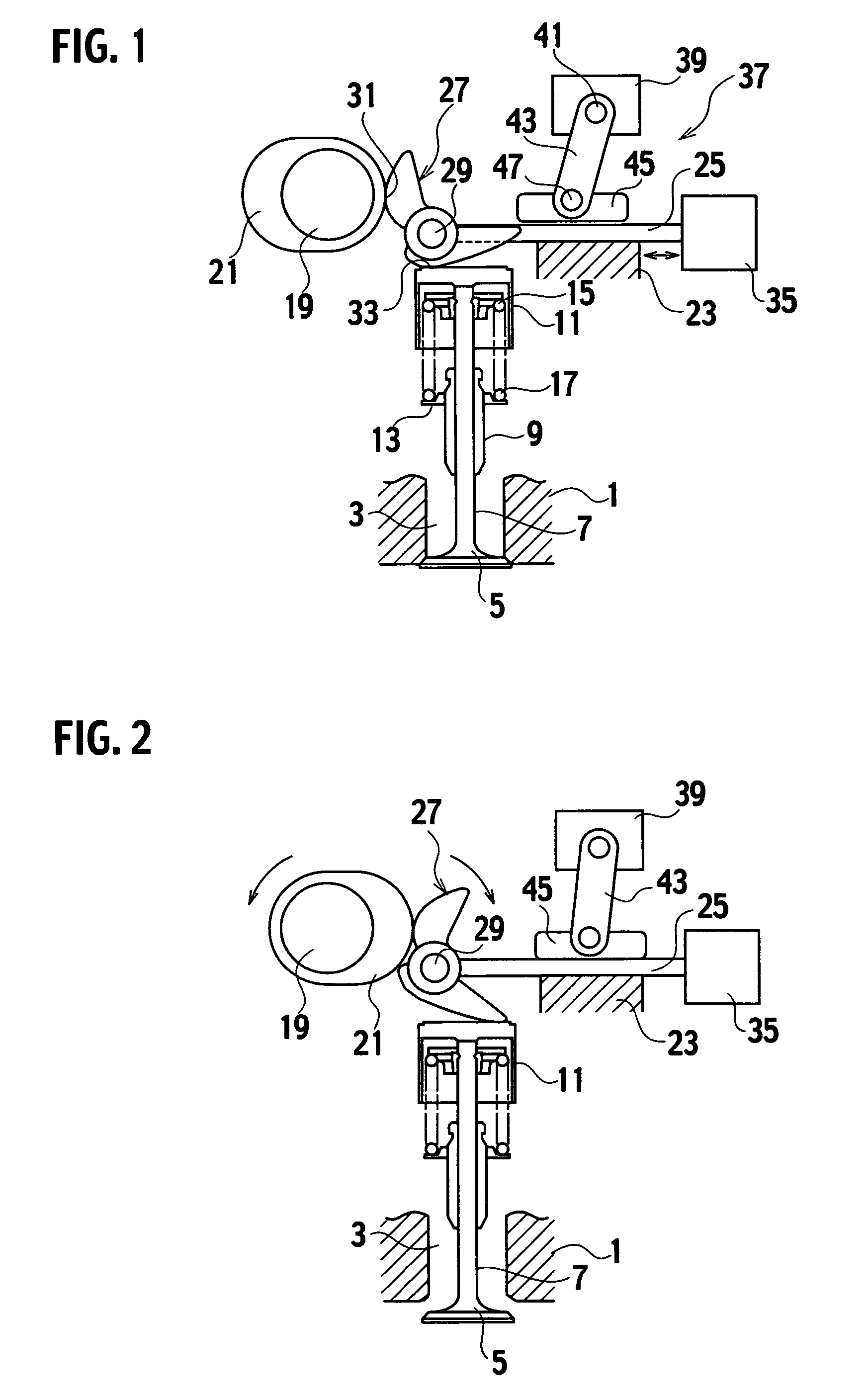
[0006] The present invention has been achieved in view of the above problems. According to the present invention, there is provided a variable valve operating device for an engine to adjust a valve lift and a valve timing of the engine, including a rocking cam which is rocked by a cam provided on a rotatable cam shaft, a rocking cam support member that rockably supports the rocking cam, a valve which is opened and closed by a rocking motion of the rocking cam, a rocking position changing unit that moves the rocking cam support member to change a lever ratio of the rocking cam and that changes a rocking position of the rocking cam, and a lock unit that can fix the rocking cam support member so as not to move during a valve-opening period of the valve.
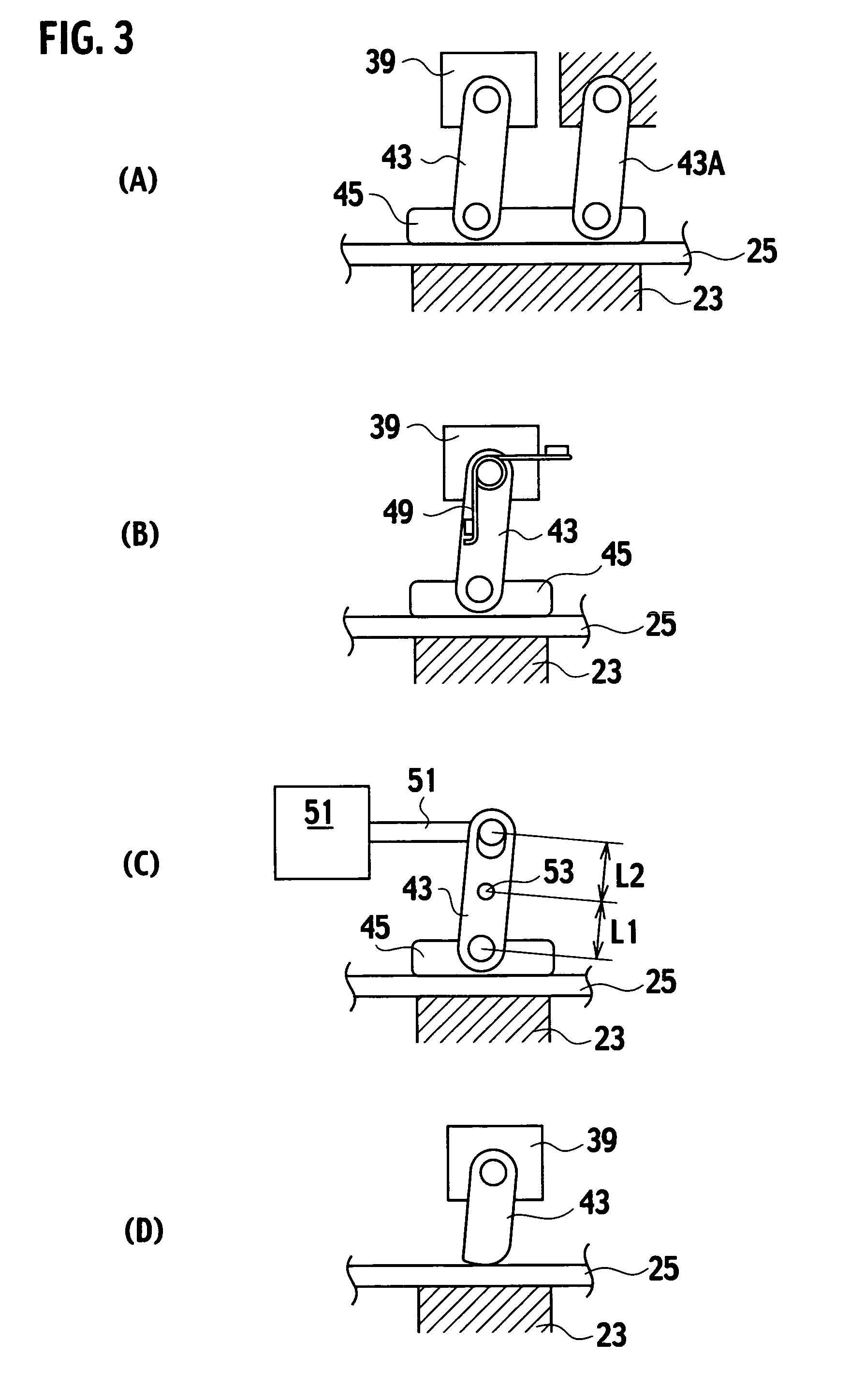
[0016] According to the present invention, there is also provided a variable valve operating device for an engine to adjust a valve lift and a valve timing of the engine, including a rocking cam which is rocked by a cam provided on a rotatable cam shaft, a rocking cam support member that rockably supports the rocking cam, a valve which is opened and closed by a rocking motion of the rocking cam, a rocking position changing unit that moves the rocking cam support member to change a rocking position of the rocking cam, and a lock unit that can fix the rocking cam support member so as not to move during a valve-opening period of the valve, wherein the rocking cam support member is disposed between a movable element which is movably provided on the rocking position changing unit and a fixed portion fixed to the rocking position changing unit, and the rocking cam support member is provided between a restriction surface provided on the movable element and the fixed portion such that the rocking cam support member can be sandwiched and fixed therebetween.
[0020] Thus, the valve is precisely opened with a lever ratio of the rocking cam which is preset by the position of the rocking cam support member. The position of the rocking cam support member is adjusted when the valve is closed, and the opening and closing timing of the valve can be swiftly adjusted.
[0021] According to the invention, since the lock unit can fix the rocking cam support member utilizing a wedge effect or a toggle link effect, it is possible to generate a great pushing force, and the rocking cam support member can be reliably fixed.

Problems solved by technology

However, this is not a configuration in which the fulcrum is fixed when the intake valve and the exhaust valve are opened and the fulcrums can be moved when the valves are closed.
However, it is necessary to demagnetize the retarder when the fulcrum is unlocked thus requiring control thereof and time therefor, which becomes a problem in enhancing the responding speed.

Method used


Image

  • Variable valve operating device for engine
  • Variable valve operating device for engine
  • Variable valve operating device for engine

Examples


second embodiment

[0070]FIGS. 4 and 5 show the present invention. Like reference signs denote constituent elements having the same functions as those of the above embodiment, and redundant explanation will be omitted.

[0071] In the second embodiment, the rocking cam 27 is integrally provided with a switch cam 55, a bellcrank-shaped rocker arm 57 is integrally provided with the push-link 43, and the rocker arm 57 is supported through a pivot 61 by a bracket 59 provided on a portion of the cylinder head such that the rocker arm 57 can rock. A biasing unit 63 such as a torsion spring is provided on a portion of the pivot 61, and the rocker arm 57 is always biased in the counterclockwise direction in FIGS. 4 and 5.

[0072] Therefore, the rocker arm 57 is supported substantially horizontally, and the rocker arm 57 is always in slide contact with a cam surface of the switch cam 55. The switch cam 55 controls the rocking motion of the rocker arm 57, and fixes the rocking cam support member 25 by the push-pad ...

third embodiment

[0077]FIGS. 6 and 7 show the present invention. Like reference signs denote constituent elements having the same functions as those of the above embodiments, and redundant explanation will be omitted.

[0078] In the third embodiment, a resilient member 65 such as a spring is resiliently provided between the rocking cam support member 25 and the rocking cam 27, the rocking cam 27 is biased in the counterclockwise direction in FIG. 7, and a lock cam 67 is turnably mounted on the support shaft 29.

[0079] The lock cam 67 is disposed between upper and lower fixing wall portions 1U and 1L formed on the cylinder head 1. A stopper 69 projects from the lock cam 67. A tip end of the stopper 69 which is formed into an appropriate cam surface can be abutted against and fixed to an upper surface of the lower fixing wall portion 1L. A resilient member 71 such as a torsion spring which biases the lock cam 67 in the clockwise direction in FIG. 7 is provided between the rocking cam support member 25 a...

fourth embodiment

[0087]FIG. 9 shows the present invention. Like reference signs denote constituent elements having the same functions as those of the above embodiments, and redundant explanation will be omitted.

[0088] The fourth embodiment is another embodiment of the rocking position changing unit 35. In the first embodiment, a resilient member 75 such as a spring that biases the rocking cam support member 25 in a direction separating from the cam shaft 19 (right direction in FIG. 9) is provided between a portion of the rocking cam support member 25 and a portion of the cylinder head 1. The fourth embodiment also has a rotatable control shaft 77 and a cam-shaped push moving positioning member 79 that can push the rocking cam support member 25 by a turning motion of the control shaft 77 as a rocking position changing unit that moves and positions the rocking cam support member 25.

[0089] The turning motion of the control shaft 77 is controlled by an actuator (not shown) such as a servomotor, and the...


PUM


Abstract

To provide a variable valve operating device that can swiftly adjust a valve timing of an engine, the variable valve operating device is for adjusting a valve lift and the valve timing of the engine. The variable valve operating device includes a rocking cam 27 which is rocked by cams 21 provided on a rotatable cam shaft 19, a rocking cam support member 25 that rockably supports the rocking cam 27, a valve 5 which is opened and closed by a rocking motion of the rocking cam 27, a rocking position changing unit 35 that moves the rocking cam support member 25 to change a lever ratio of the rocking cam 27 and that changes a rocking position of the rocking cam 27, and a lock unit 37 that can fix the rocking cam support member 25 so as not to move during a valve-opening period of the valve 5. The lock unit 37 includes a support base 23 that movably supports the rocking cam support member 25, and a push-link 43 which is rocked by an actuator 39. When a tip end of the push-link 43 abuts against the rocking cam support member 25, the push-link 43 pushes the rocking cam support member 25 toward the support base 23.

Description

TECHNICAL FIELD [0001] The present invention relates to a variable valve operating device for an engine to adjust an opening and closing timing and a valve lift amount of an intake valve and an exhaust valve provided in the engine, and more particularly, to an adjusting device of a valve lift and a valve timing of an engine in which a valve timing cannot be adjusted during a valve-opening period of the intake valve, the exhaust valve, and the like, and the valve timing can be adjusted during a valve-closing period thereof. BACKGROUND ART [0002] As a conventional configuration for opening and closing an intake valve and an exhaust valve provided in an engine, it is general to apply a rocking motion to a rocker arm by a cam provided on a rotatable cam shaft, and to push valve tappets of the intake valve and the exhaust valve by a tip end of the rocker arm, thereby opening and closing the intake valve and the exhaust valve. As a configuration for adjusting the valve lift and the valve ...

Claims


Application Information

Patent Timeline
Patent Type & Authority Applications(United States)
IPC IPC(8): F01L1/34F01L1/02F01L13/00
CPCF01L1/08F01L2820/032F01L13/0063
Inventor MURAJI, TETSUONISHIMOTO, YUKINORIUCHI, HIROTOSHONO, HIDEKI
Owner MIKUNI CORP
Why Eureka
Try Eureka