User interface and head gear for a continuous positive airway pressure device

a positive airway and user interface technology, applied in the field of patient ventilation systems, can solve the problems of poor judgment, severe and even life-threatening consequences, irritability, etc., and achieve the effects of minimizing gravitational and inertial forces, eliminating problems, and low mass

Inactive Publication Date: 2007-07-19
CAREFUSION
View PDF31 Cites 215 Cited by
  • Summary
  • Abstract
  • Description
  • Claims
  • Application Information

AI Technical Summary

Benefits of technology

[0019] In this regard, the patient hose is a relatively short section and is therefore of relatively low mass in order to minimize gravitational and inertial forces acting upon the nasal mask or nasal prongs and to eliminate problems associated with lateral tugging or torqueing on the nasal mask or prongs as is common in conventional CPAP devices.
[0020] In an optional configuration, the patient hose may be comprised of a series of ball joints disposed end-to-end wherein each ball joint includes a sleeve member that is swivelably coupleable to an adjacent ball member. This arrangement allows for specific tailoring of the length of the patient hose as well as accommodating a wider range of motion of the patient's head without tugging by the patient hose on the mask. The patient hose can be provided in any desired length suitable for off-patient use of the CPAP device. For example, the CPAP device may be placed near the patient such as on a pillow in the patient's bed while the patient is sleeping. The flexibility provided by the ball joints and the low mass of the relatively short patient hose results in a high degree of movement for the patient without problems of air leakage around the mask or pressure points on the patient's face as are more commonly associated with conventional CPAP devices.
[0021] Resilient cheek pads may be included with the user interface and are preferably rotatably connectable thereto such as at opposing end portions of the manifold member. The cheek pads may be configured to anatomically conform to a variety of facial structures and assist in stabilizing the user interface in a comfortable position regardless of patient movement. The rotatable swivelable nature of the cheek pads is facilitated by mounting the cheek pads on a connector at each of opposing end portions of the manifold member. The connectors are releasably securable to the manifold member through a ball and socket joint wherein the socket is preferably sized to frictionally engage the ball such that the connector maintains any orientation set by the patient.
[0022] The cheek pads may be provided in a variety of sizes, shapes and configurations and may be fabricated using different materials. For example, the cheek pads may be formed of foam or deformable plastic to conform to the patient's face. Attachment and removal of the cheek pads from the connectors is facilitated through the use of mounting s

Problems solved by technology

Left untreated, OSA can lead to severe and even life-threatening consequences.
Serious cases of OSA can result in sleep deprivation or insomnia which, over time, can result in moodiness, irritability, memory loss, poor judgment and an overall poor quality of life.
Even further, patients suffering from OSA have a dramatically increased risk of traffic accidents and an increased mortality rate due to medical complications stemming from this disorder.
The torqueing or pulling by the patient hose results in poor sealing of the mask against the patient's face.
In addition, the sideways pulling on the mask may also create pressure points against the patient's face and results in general patient discomfort.
For patients who use nasal prongs, the sideways tugging can cause irritation of the patient's nose due to the close-fitting engagement of the prongs with tender mucous tissue lining the patient's nostrils.
For patients who use a nasal mask which seals around an exterior of the patient's nose, the tugging of the patient hose can prevent proper sealing of the mask and can also cause eye irritation as a result of pressurized gas leak

Method used


Image

  • User interface and head gear for a continuous positive airway pressure device
  • User interface and head gear for a continuous positive airway pressure device
  • User interface and head gear for a continuous positive airway pressure device

Examples


Embodiment Construction

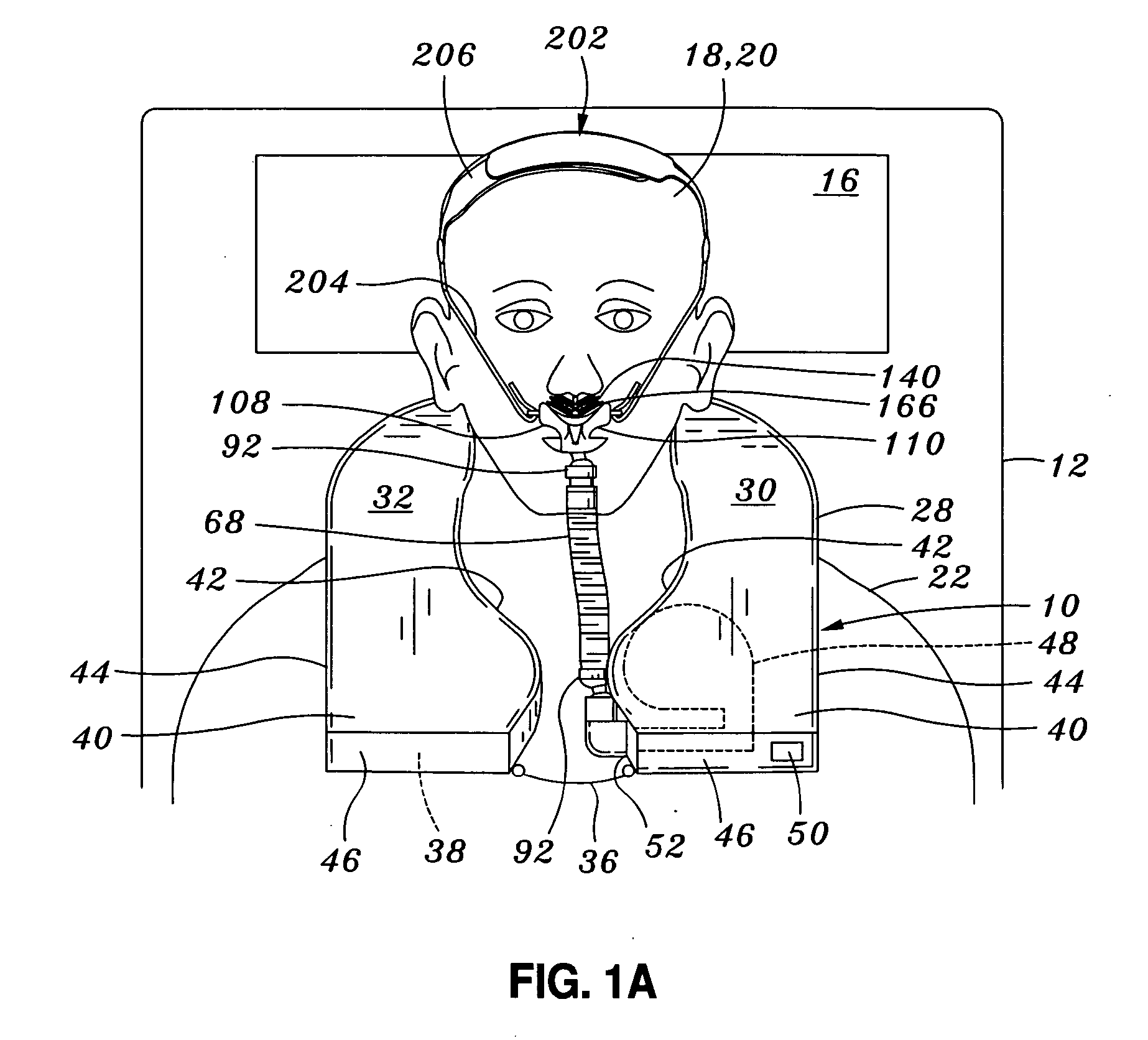
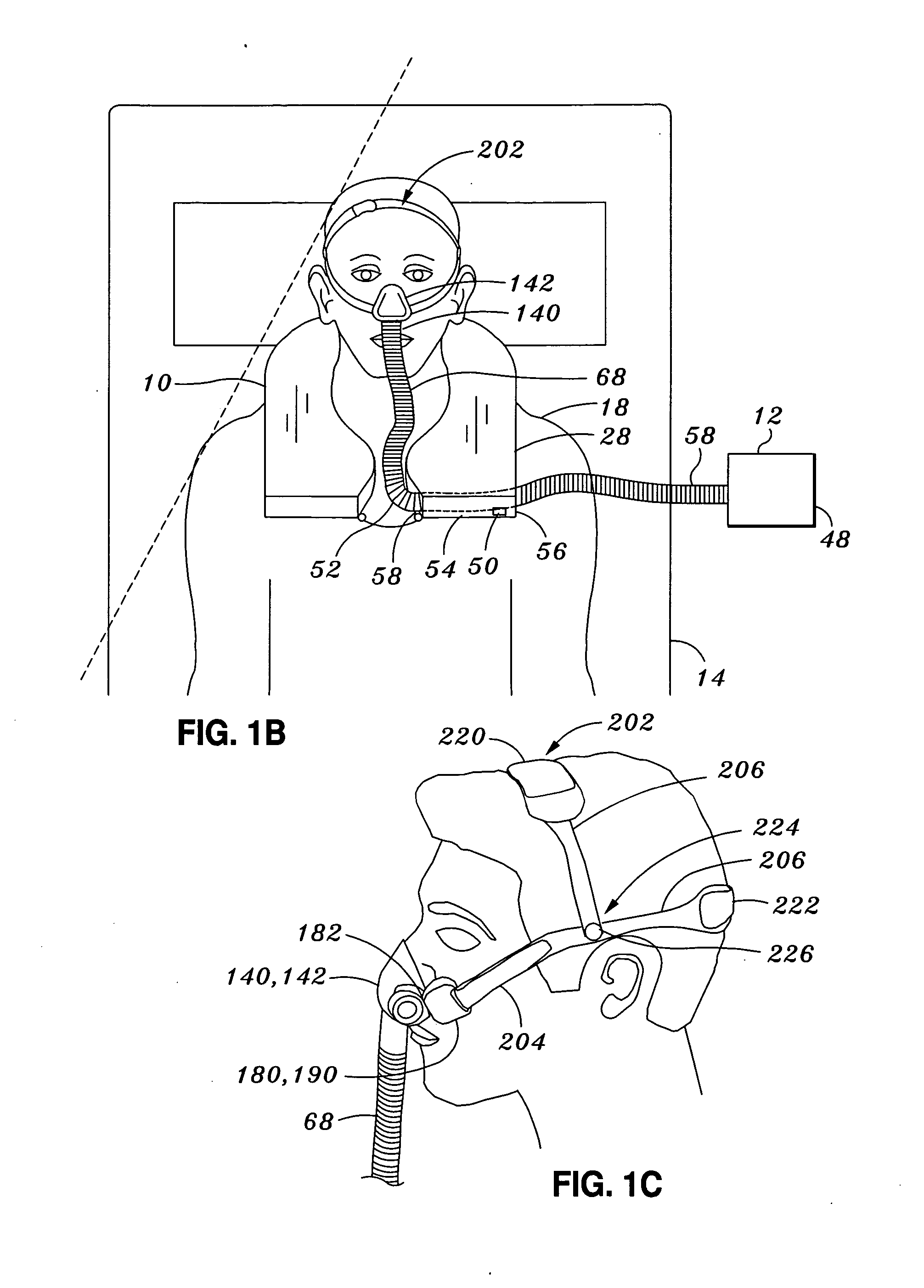
[0058] Referring now to the drawings wherein the showings are for purposes of illustrating preferred embodiments of the present invention and not for purposes of limiting the same, shown in FIGS. 1A, 1B and 1D is a continuous positive airway pressure (CPAP) device which is ergonomically-designed in a self-contained vest-like arrangement which may be worn (FIGS. 1A-B) or operated near a patient 18 (FIG. 1D). The figures further illustrate a user interface 108 as may be used with the portable CPAP device 10 or with alternative ventilation systems.

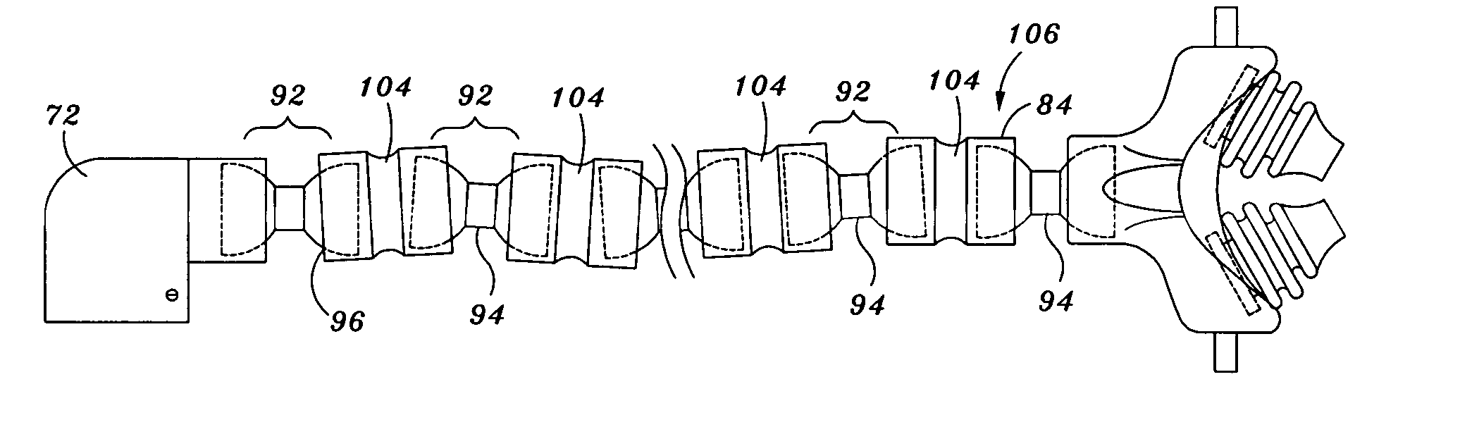
[0059] The user interface 108 may be provided in kit form and generally comprises a manifold member 110 and a gas delivery member 140. The gas delivery member 140 is providable in a variety of alternative configurations such as a nasal mask 142 or nasal prongs 166 and both are configured to be interchangeably mountable to the manifold member 110 at the patient's discretion. As can be seen in FIG. 1A, a ball joint 92 may be included between t...


PUM


Abstract

A user interface for a portable continuous positive airway pressure (CPAP) device comprises a gas delivery member releasably mountable to a manifold member. The CPAP device comprises a motor blower unit contained in a wearable vest which is connectable by a patient hose to the user interface. Alternative embodiments of the gas delivery member include a nasal mask or a pair of nasal prongs which are interchangeably mountable to the manifold member. Ball joints on opposing ends of the patient hose swivelably interconnect the patient hose to the user interface and to the motor blower unit. Cheek pads extend from opposing ends of the manifold member and are freely orientatable relative thereto. Six-way adjustable head gear stabilizes the user interface on the patient's face and comprises side straps and head straps which are pivotably joined to one another and which are adjustable lengthwise to fit a wide range of patient

Description

CROSS-REFERENCE TO RELATED APPLICATIONS [0001] The present application claims priority to U.S. Provisional Application No. 60 / 758,151, filed on Jan. 11, 2006, and to U.S. Provisional Application No. 60 / 793,704, filed on Apr. 20, 2006, the entire contents of the each provisional application being expressly incorporated by reference herein. The present application is related to U.S. Utility Patent Application Ser. No. 11 / 128,552 entitled PORTABLE CONTINUOUS POSITIVE AIRWAY PRESSURE SYSTEM and filed on May 13, 2005, the entire contents of which is expressly incorporated by reference herein. STATEMENT RE: FEDERALLY SPONSORED RESEARCH / DEVELOPMENT [0002] (Not Applicable) BACKGROUND [0003] The present invention relates generally to patient ventilation systems and, more particularly, to a uniquely-configured user interface and fully-adjustable head gear as may be used with a portable continuous positive airway pressure (CPAP) device. The user interface and head gear are specifically adapted...

Claims


Application Information

Patent Timeline
IPC IPC(8): A62B7/00A61M15/08
CPCA61M16/0066A61M16/06A61M16/0666A61M16/0616A61M16/08A62B18/006A61M16/0825A61M16/0683A61M2205/0216A61M16/0611
Inventor HOFFMAN, LESLIE
Owner CAREFUSION
Why Eureka
Try Eureka