Device for measuring current

a current measurement and current technology, applied in the direction of magnetic property measurement, material magnetic variables, instruments, etc., can solve the problem that the external magnetic field is hardly screened

Active Publication Date: 2007-07-19
MELEXIS TECH NV
View PDF13 Cites 23 Cited by
  • Summary
  • Abstract
  • Description
  • Claims
  • Application Information

AI Technical Summary

Problems solved by technology

Disadvantages of this current sensor are that because of its construction as current sensor with integrated current conductor it is only suited for measuring relatively small currents of up to 20 A and that external magnetic fields are hardly screened.

Method used


Image

  • Device for measuring current
  • Device for measuring current
  • Device for measuring current

Examples


Embodiment Construction

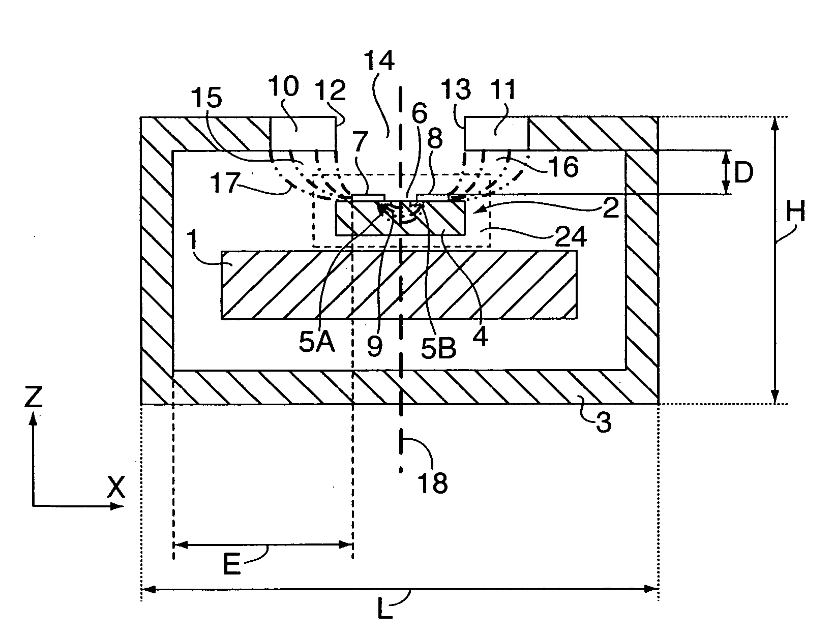
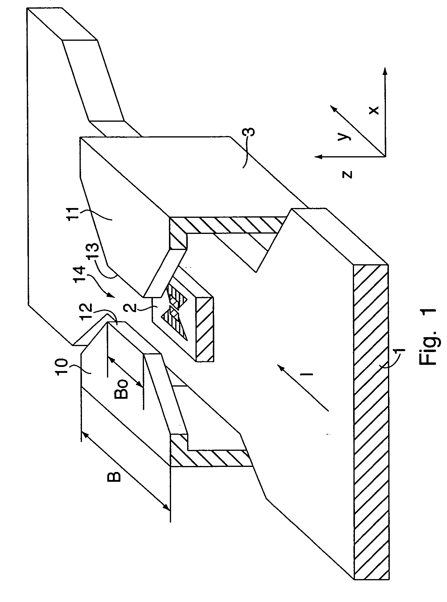
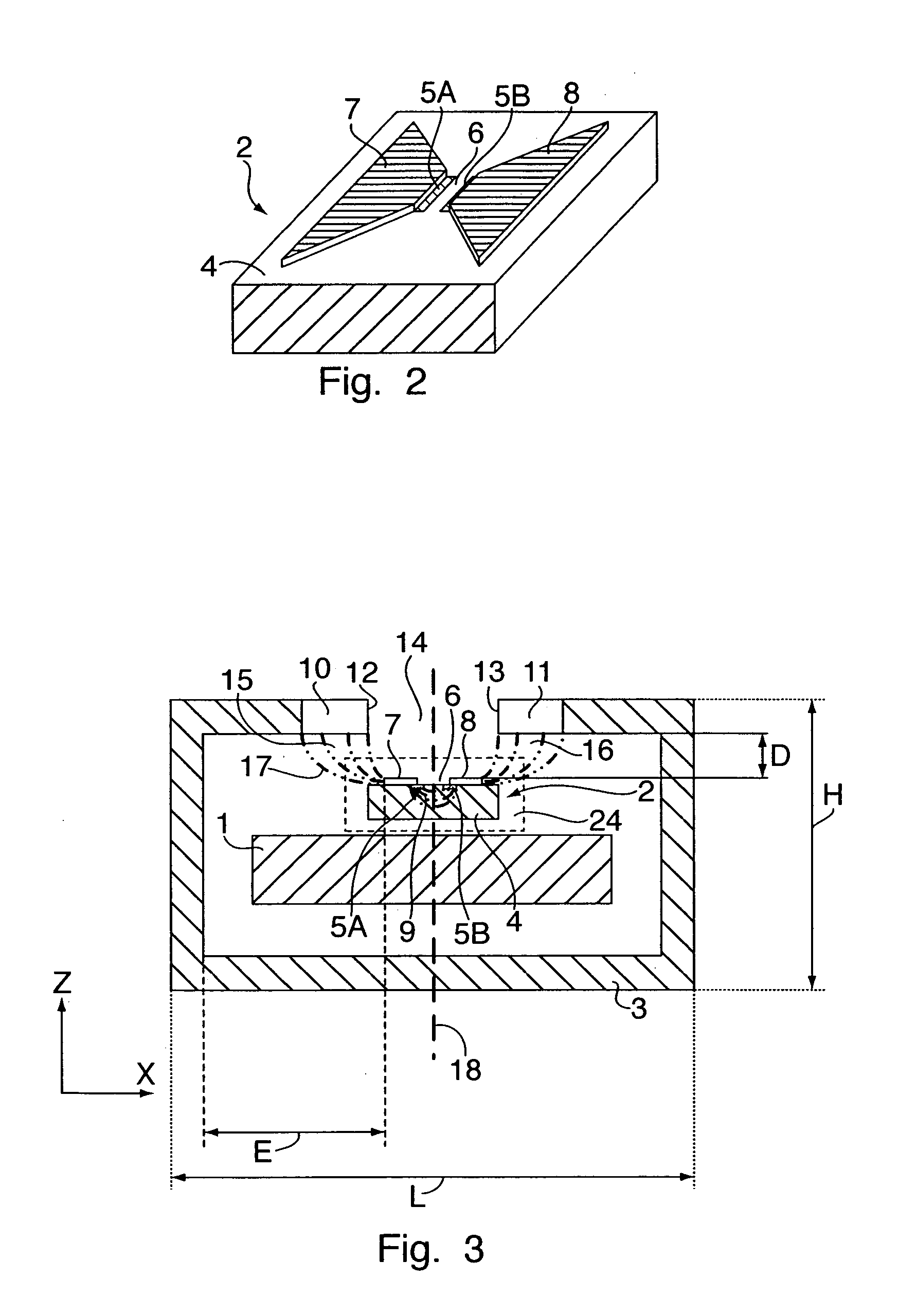
[0020]FIGS. 1 and 3 show a perspective view or cross-section, respectively, of a device for measuring the current I flowing through a current conductor 1, that in accordance with the invention is designed for the measurement of a current in the range from 0 to typically 20 A or 50 A, or about 100 A in the maximum. The cross-section of the current conductor 1 is preferably rectangular, but it may also have an arbitrary other shape, for example a round shape. The coordinates in a Cartesian coordinate system are designated with x, y and z. The current flows in the y-direction. The device for measuring current comprises a magnetic field sensor 2 that measures the magnetic field produced by the current I and a yoke 3 of a material with high magnetic permeability. High permeability means a relative permeability of at least 100 (the relative permeability of air is 1). The yoke 3 is formed for example from a piece of sheet metal of iron or Permalloy or Mumetal if this, that typically have a...


PUM


Abstract

A device for measuring current comprises a magnetic field sensor (2) for measuring the magnetic field produced by a current I flowing through a current conductor (1) and a yoke (3) of a magnetic material with a relative permeability of at least 100. The magnetic field sensor (2) preferably comprises a semiconductor chip with at least one Hall element and an electronic circuit for the operation of the Hall element. Two magnetic field concentrators (7, 8) separated by an air gap (6) are arranged on a surface of the semiconductor chip such that field lines (9) of the magnetic field (see FIG. 3) that issue from the first magnetic field concentrator (7) in the vicinity of the air gap (6) and impinge on the second magnetic field concentrator (8) in the vicinity of the air gap (6) pass through the at least one Hall element. The yoke (3) consists of an oblong piece of sheet metal or a laminate of sheet metals with two ends (10, 11) that has been brought by bending into a form with which the front sides of the ends (10, 11) of the yoke (3) lie opposite each other and are separated by an air gap (14). The ends (10, 11) of the yoke (3) are tapered so that a width of the ends of the yoke is less than a width of the yoke.

Description

PRIORITY CLAIM[0001]Applicant hereby claims foreign priority under 35 U.S.C § 119 from Swiss Patent Application No. 96 / 06 filed Jan. 19, 2006, Swiss Patent Application No. 739 / 06 filed May 8, 2006 and Swiss Patent Application No. 985 / 06 filed Jun. 14, 2006, the disclosures of which are herein incorporated by reference.FIELD OF THE INVENTION[0002]The invention concerns a device for measuring current.BACKGROUND OF THE INVENTION[0003]Such a device for measuring current can also be designated as a current sensor, in particular then if it can be sold in the trade as a product consisting of one single component. Such a one-piece current sensor is known from U.S. Pat. No. 5,942,895. The current sensor consists of a current conductor, a magnetic field sensor for measuring the magnetic field produced by a current flowing through the current conductor and a ferromagnetic yoke. The magnetic field sensor contains a semiconductor chip with two magnetic field concentrators arranged on the surface...

Claims


Application Information

Patent Timeline
Patent Type & Authority Applications(United States)
IPC IPC(8): G01R11/32
CPCG01R15/185G01R15/207G01R15/202
Inventor RACZ, ROBERTHUBER, SAMUELGLOOR, MARKUS
Owner MELEXIS TECH NV
Why Eureka
Try Eureka