Methods and apparatus for determining the size and shape of particles

a particle size and shape technology, applied in particle and sedimentation analysis, measurement devices, instruments, etc., can solve the problem of limiting the size dynamic range of a single measurement, and achieve the effect of reducing statistical count uncertainty and improving the dynamic range of coun

Active Publication Date: 2007-07-19
TRAINER MICHAEL
View PDF6 Cites 87 Cited by
  • Summary
  • Abstract
  • Description
  • Claims
  • Application Information

AI Technical Summary

Problems solved by technology

This large range of counts and the Poisson statistics of the counting process limit the size dynamic range for a single measurement.

Method used


Image

  • Methods and apparatus for determining the size and shape of particles
  • Methods and apparatus for determining the size and shape of particles
  • Methods and apparatus for determining the size and shape of particles

Examples


Embodiment Construction

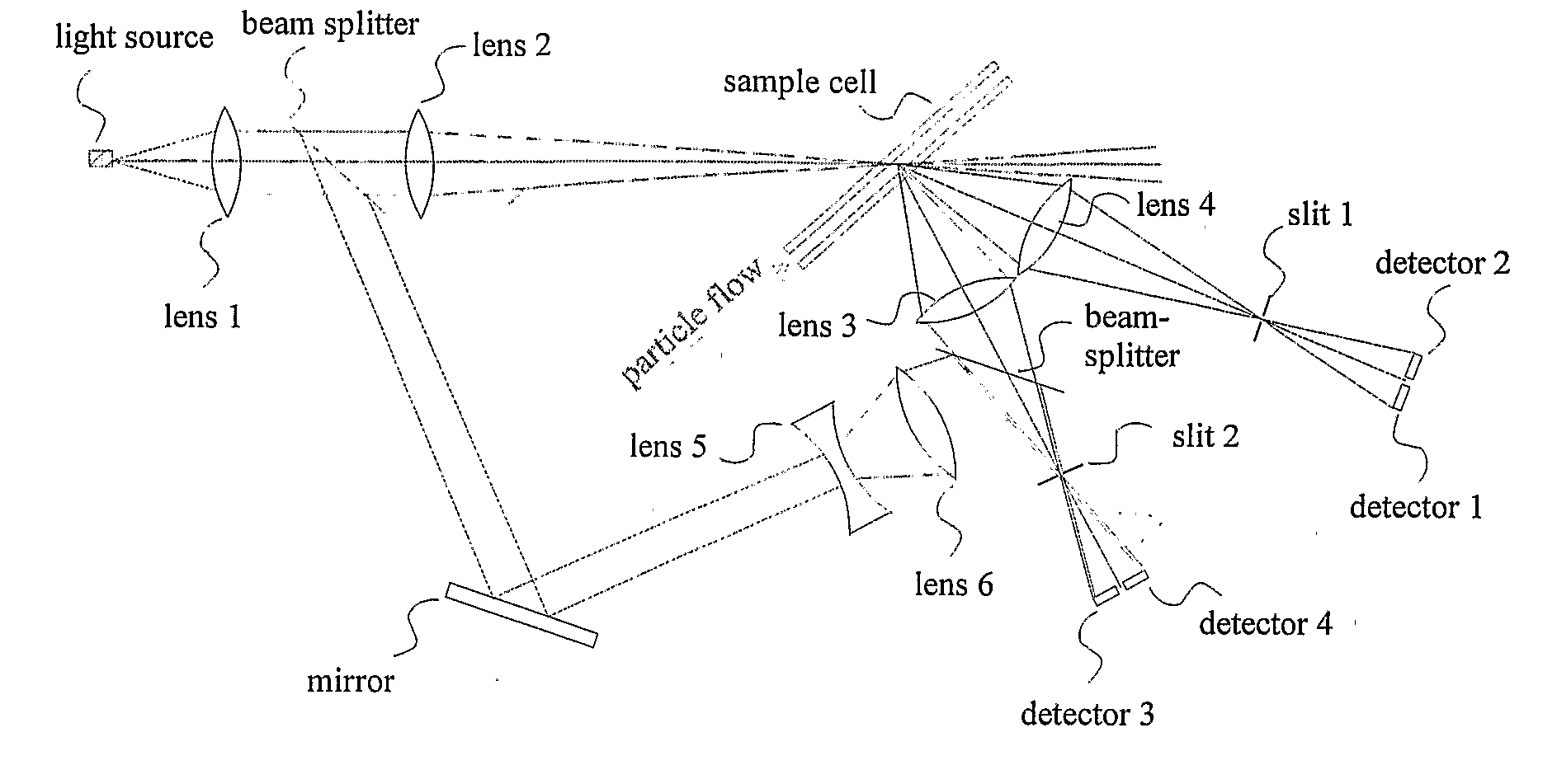
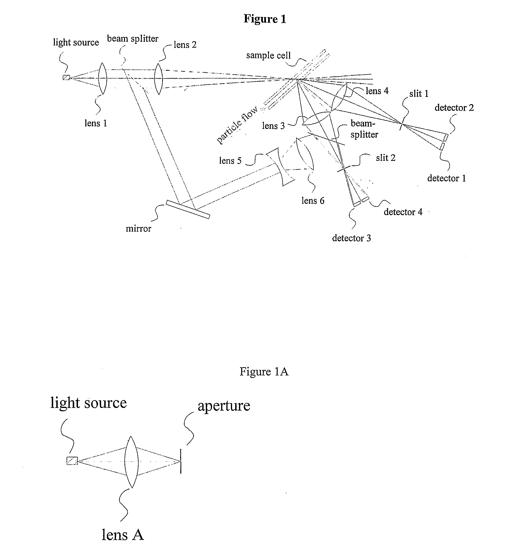
[0004] Light scattered from the large diameter beam should be measured at low scattering angles to sense large particles. The optical pathlength of this beam in the particle sample must be large enough to pass the largest particle of interest for that beam. For small particles, the interaction volume in the beam must be reduced along all three spatial directions. The beam crossection is reduced by an aperture or by focusing the beam into the interaction volume. The interaction volume is the intersection of the incident light beam and the field of view for the detector which measures scattered light from the particle. However, for very small particles, reduction of the optical path along the beam propagation direction is limited by the gap thickness through which the sample must flow. This could be accomplished by using a cell with various pathlengths or a cell with a wedge shaped window spacing (see FIG. 9b) to provide a range of optical pathlengths. Smaller source beams would pass ...


PUM

PropertyMeasurementUnit
particle diameteraaaaaaaaaa
refractive indexaaaaaaaaaa

Abstract

An instrument for measuring the size distribution of a particle sample by counting and classifying particles into selected size ranges. The particle concentration is reduced to the level where the probability of measuring scattering from multiple particles at one time is reduced to an acceptable level. A light beam is focused or collimated through a sample cell, through which the particles flow. As each particle passes through the beam, it scatters, absorbs, and transmits different amounts of the light, depending upon the particle size. So both the decrease in the beam intensity, due to light removal by the particle, and increase of light, scattered by the particle, may be used to determine the particle size, to classify the particle and count it in a certain size range. If all of the particles pass through a single beam, then many small particles must be counted for each large one because typical distributions are uniform on a particle volume basis, and the number distribution is related to the volume distribution by the particle diameter cubed.

Description

RELATED APPLICATIONS [0001] This applications claims priority of U.S. Provisional Patent Application No. 60 / 550,591, filed Mar. 6, 2004TECHNICAL FIELD OF THE INVENTION [0002] In general, the present invention relates to systems and methods that analyze particles in a sample using laser light diffraction. More particularly, the present invention relates to systems and methods that analyze laser light diffraction patterns to determine the size of particles in a sample. DISCLOSURE OF THE INVENTION [0003] This disclosure describes an instrument for measuring the size distribution of a particle sample by counting and classifying particles into selected size ranges. The particle concentration is reduced to the level where the probability of measuring scattering from multiple particles at one time is reduced to an acceptable level. A light beam is focused or collimated through a sample cell, through which the particles flow. As each particle passes through the beam, it scatters, absorbs, a...

Claims


Application Information

Patent Timeline
Patent Type & Authority Applications(United States)
IPC IPC(8): G01N15/02G01N15/14
CPCG01N15/0205G01N15/1459G01N2015/1497G01N2015/1493G01N2015/1486G01N15/0211G01N15/1463
Inventor TRAINER, MICHAEL
Owner TRAINER MICHAEL
Why Eureka
Try Eureka