
Wind turbine

a technology of turbine blades and turbine blades, which is applied in the field of fluid-driven turbines, can solve the problems of reducing blade pitch, reducing blade pitch, and reaching the practicable limit, and achieve the effect of large deflection surface area

Active Publication Date: 2007-07-19
WILLIAMS HERBERT L
View PDF13 Cites 34 Cited by
  • Summary
  • Abstract
  • Description
  • Claims
  • Application Information

AI Technical Summary

Benefits of technology

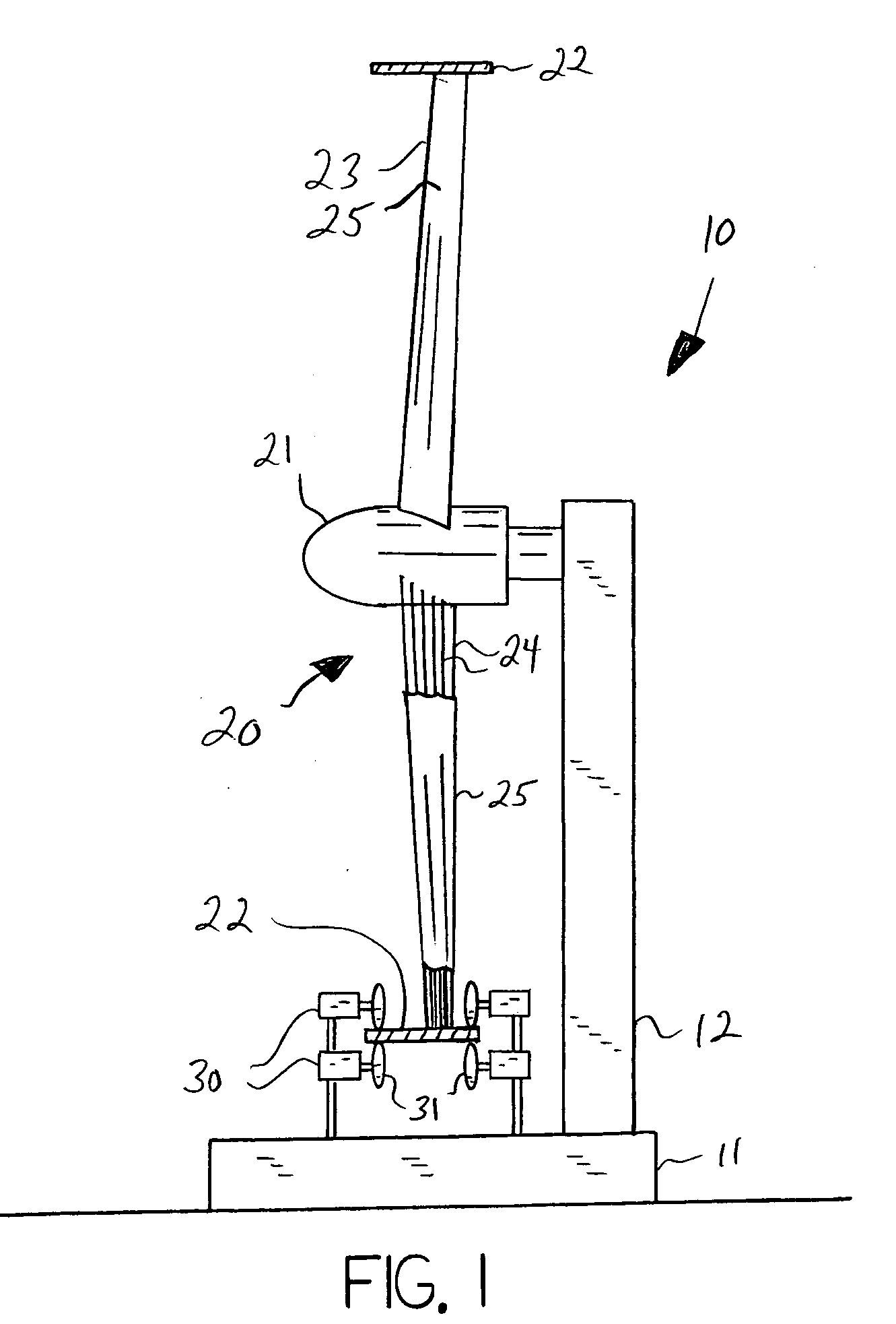
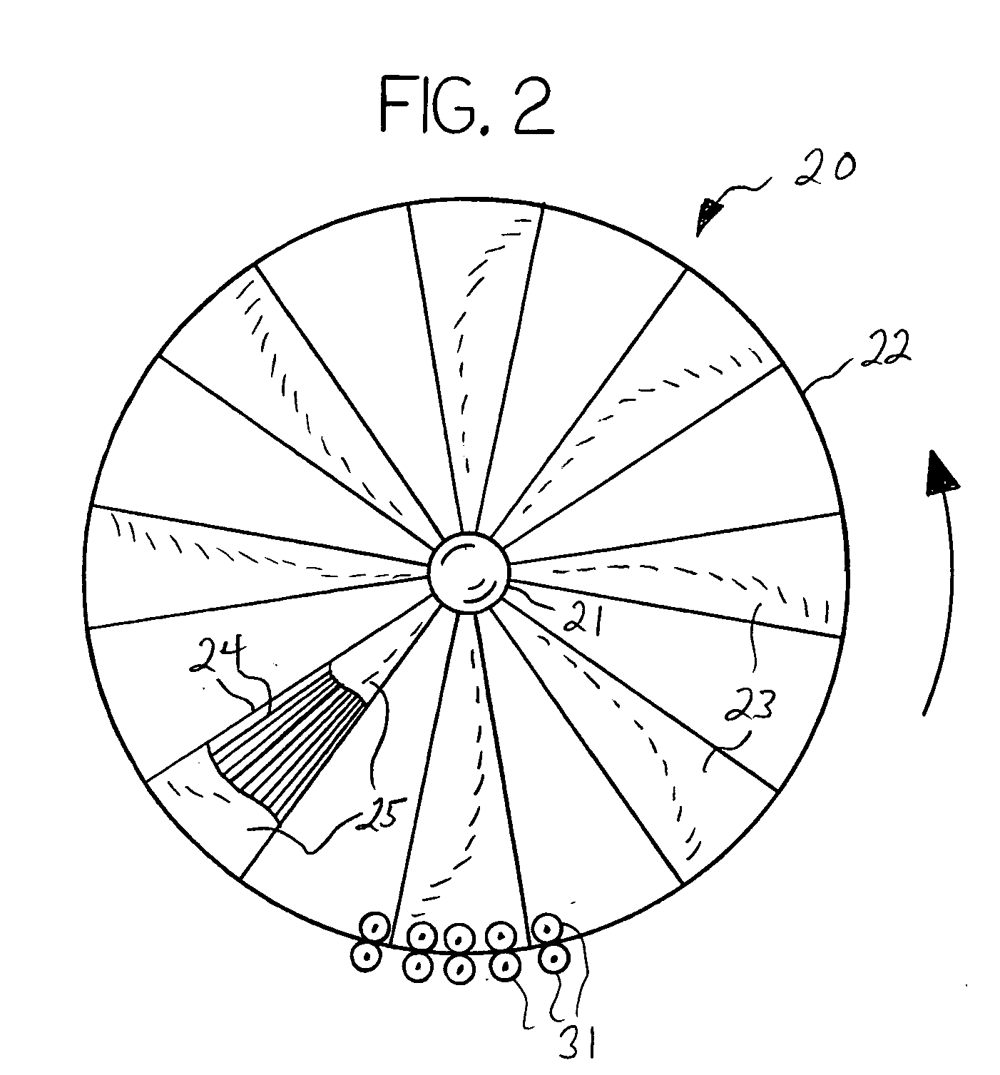
"The invention is a fluid powered turbine that generates electrical power from wind or water flow. It consists of a rotor assembly with a central hub member and a rotating annular rim member, which are joined by a plurality of blade members. Each blade member consists of greater than two cable members and a skin member disposed thereon, which encases the cable members. The blade members are mounted on the hub member and rim member in various configurations and numbers, and the surface configuration and pitch of the blade member can be chosen to maximize efficiency. The invention is a fluid turbine powered by wind or water that generates electrical power."

Problems solved by technology

This size creates a problem, in that each blade must act as a cantilever that can support the elongated blade and the blades must be increasingly massive toward the central hub in order to preclude the blade from breaking during use.
Even with the use of high tech composites, carbon fibers and the like, a practical limit has been reached.
Reduced rpm's require larger reduction gearboxes, which is undesirable.
Decreasing blade pitch in order to increase the rpm's reduces torque, which is undesirable.
Such wind turbines are often of smaller size and utilize sails rather than blades in order to increase the number of wind catching elements, since the weight of the annular rim adds structural problems to the design.

Method used


Image

  • Wind turbine
  • Wind turbine
  • Wind turbine

Examples


Embodiment Construction

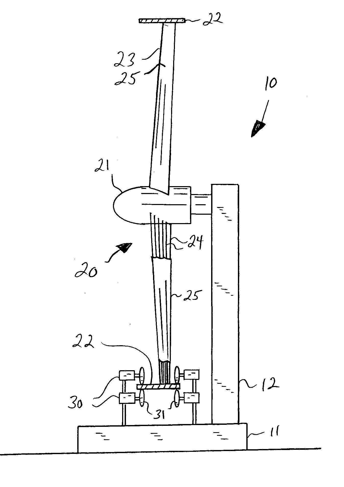
[0020] With reference to the drawings, the invention will now be described in detail with regard for the best mode and the preferred embodiment. In a broad sense, the invention is a fluid powered turbine, such as a wind turbine or a water turbine, where airflow or water flow rotates a rotor element about a central shaft or hub member, whereby electrical power or the like is generated by the rotational energy, and wherein the rotor element comprises a plurality of blade members extending from the rotating central hub member to a rotating annular rim member. For simplicity herein, the invention shall be described using wind as the fluid medium, but it is to be understood that the invention is operational as well with a flowing liquid, such as water.

[0021] As shown in FIGS. 1 and 2, the invention is a turbine 10 comprising a rotor assembly 20 mounted onto a fixed support means, shown as comprising a base member 11 and a tower member 12, whereby the rotor assembly 20 is positioned to h...


PUM


Abstract

A fluid turbine, such as a wind or hydro turbine, for generating electrical power, the turbine having a rotor assembly comprising a hub, a rim and a plurality of tensioned cable members joining them together, the cable members being grouped into sets to define a plurality of supports for individual skin members to create a plurality of lightweight blade members.

Description

BACKGROUND OF THE INVENTION [0001] The invention relates generally to the field of fluid driven turbines, such as wind turbines or water turbines, wherein electrical power is generated from airflow or water flow across rotor blades. More particularly, the invention relates to such turbines wherein the blades extend from a central rotating hub or shaft member to an annular rotating ring or rim member. [0002] Wind turbines, also known as windmills, wind generators, wind machines or the like, are well known devices for producing energy, typically electrical energy, by harnessing the power of wind. Wind turbines used to generate large amounts of energy are very large structures, standing hundreds of feet tall and having rotor blades extending hundreds of feet, the rotor blades being mounted to a central hub or shaft. Large elongated blades are required since the area of blade sweep is proportional to the power that can be produced by a given wind turbine. This size creates a problem, in...

Claims


Application Information

Patent Timeline
Patent Type & Authority Applications(United States)
IPC IPC(8): F03D7/02
CPCF03D1/0675F03D1/0683Y02E10/721F05B2240/30Y02B10/30F05B2210/16Y02E10/72Y02P70/50F03D7/02
Inventor WILLIAMS, HERBERT L.
Owner WILLIAMS HERBERT L
Learn More